Dell Inspiron Mini 10 1010 Service Manual - Page 14
in-1 Memory and Processor Board
 |
View all Dell Inspiron Mini 10 1010 manuals
Add to My Manuals
Save this manual to your list of manuals |
Page 14 highlights
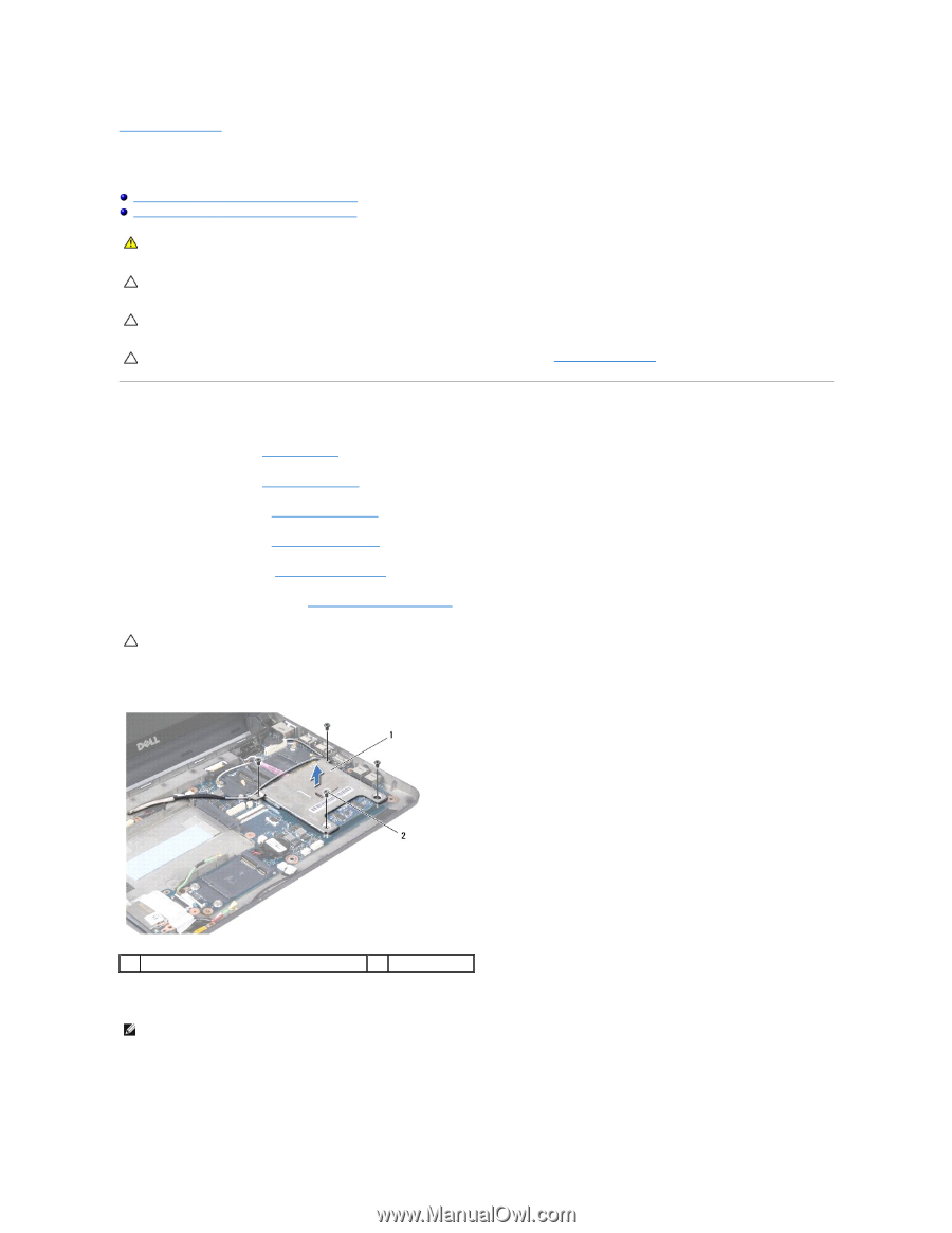
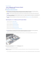
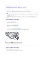
Back to Contents Page 2-in-1 Memory and Processor Board Dell™ Inspiron™ 1010 Service Manual Removing the 2-in-1 Memory and Processor Board Replacing the 2-in-1 Memory and Processor Board WARNING: Before working inside your computer, read the safety information that shipped with your computer. For additional safety best practices information, see the Regulatory Compliance Homepage at www.dell.com/regulatory_compliance. CAUTION: To avoid electrostatic discharge, ground yourself by using a wrist grounding strap or by periodically touching an unpainted metal surface. CAUTION: Only a certified service technician should perform repairs on your computer. Damage due to servicing that is not authorized by Dell™ is not covered by your warranty. CAUTION: To help prevent damage to the system board, remove the main battery (see Removing the Battery) before working inside the computer. Removing the 2-in-1 Memory and Processor Board 1. Follow the instructions in Before You Begin. 2. Remove the battery (see Removing the Battery). 3. Remove the keyboard (see Removing the Keyboard). 4. Remove the palm rest (see Removing the Palm Rest). 5. Remove the hard drive (see Removing the Hard Drive). 6. Remove the palm rest bracket (see Removing the Palm Rest Bracket). CAUTION: When the 2-in-1 memory and processor board is removed from the computer, store it in protective antistatic packaging (see "Protecting Against Electrostatic Discharge" in the safety instructions that shipped with your computer). 7. Remove the four screws that secure the processor system board cover and the 2-in-1 memory and processor board to the system board. 1 processor system board cover 2 screws (4) 8. Remove the two thermal pads on the processor. NOTE: The thermal pads may stick to the bottom of the processor system board cover. Remove the thermal pads from the bottom of the processor system board cover. 9. Use your fingertips to carefully spread apart the securing clips on either side of 2-in-1 memory and processor board connector until the board pops up.
-
 1
1 -
2
-
3
-
4
-
5
-
6
-
7
-
8
-
 9
9 -
 10
10 -
 11
11 -
 12
12 -
 13
13 -
 14
14 -
 15
15 -
 16
16 -
 17
17 -
 18
18 -
 19
19 -
20
-
21
-
22
-
23
-
24
-
25
-
26
-
27
-
28
-
29
-
30
-
31
-
32
-
33
-
34
-
35
-
36
-
37
-
38
-
39
-
40
-
41
-
42
-
43
-
44
 |
 |