Dell Latitude D630 Service Manual - Page 39
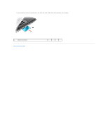
System Board - cooling fan
 |
UPC - 683728230456
View all Dell Latitude D630 manuals
Add to My Manuals
Save this manual to your list of manuals |
Page 39 highlights
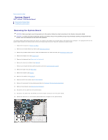
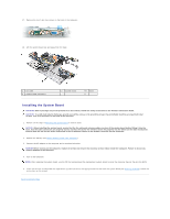
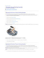
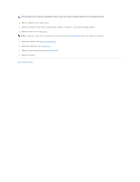
Back to Contents Page System Board Dell™ Latitude™ D630 Service Manual Removing the System Board Installing the System Board Removing the System Board CAUTION: Before you begin any of the procedures in this section, follow the safety instructions in the Product Information Guide. CAUTION: To avoid electrostatic discharge, ground yourself by using a wrist grounding strap or by periodically touching an unpainted metal surface, such as a connector on the back of the computer. The system board's BIOS chip contains the Service Tag, which is also visible on a barcode label on the bottom of the computer. The replacement kit for the system board includes a CD that provides a utility for transferring the Service Tag to the replacement system board. 1. Follow the instructions in Before You Begin. 2. Remove any installed media bay device (see Media Bay Devices). 3. Remove any installed smart cards or smart card blanks from the smart card slot (see Removing a Smart Card). 4. Remove the hinge cover (see Hinge Cover). 5. Remove the keyboard (see Removing the Keyboard). 6. Remove the memory module(s) (see Memory). 7. Remove any installed wireless communications cards (see Communications Cards). 8. Remove the palm rest (see Palm Rest). 9. Remove the modem (see Modem). 10. Remove the speaker (see Speaker). 11. Remove the PC Card reader (see PC Card Reader). 12. Remove the processor thermal-cooling assembly (see Processor Thermal-Cooling Assembly). 13. Remove the processor (see Removing the Processor). 14. Disconnect the fan cable from the system board. 15. Disconnect the cables near the WLAN card and the modem connector from the system board. 16. Remove the four M2.5 x 5-mm screws (labeled with silver triangles on the system board).
-
 1
1 -
2
-
3
-
4
-
5
-
6
-
7
-
8
-
9
-
10
-
11
-
12
-
13
-
14
-
15
-
16
-
17
-
18
-
19
-
20
-
21
-
22
-
23
-
24
-
25
-
26
-
27
-
28
-
29
-
30
-
31
-
32
-
33
-
 34
34 -
 35
35 -
 36
36 -
 37
37 -
 38
38 -
 39
39 -
 40
40 -
 41
41 -
 42
42 -
 43
43
 |
 |
