Dell Latitude D630 Service Manual - Page 9
Processor
 |
UPC - 683728230456
View all Dell Latitude D630 manuals
Add to My Manuals
Save this manual to your list of manuals |
Page 9 highlights
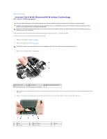
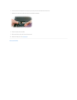
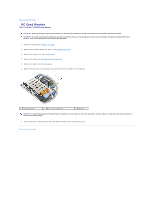
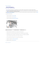
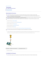
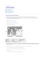
Back to Contents Page Processor Dell™ Latitude™ D630 Service Manual Removing the Processor Installing the Processor Removing the Processor CAUTION: Before you begin any of the procedures in this section, follow the safety instructions in the Product Information Guide. CAUTION: To avoid electrostatic discharge, ground yourself by using a wrist grounding strap or by periodically touching an unpainted metal surface, such as a connector on the back of the computer. NOTICE: To prevent intermittent contact between the ZIF-socket cam screw and the processor when removing or replacing the processor, press to apply slight pressure to the center of the processor while turning the cam screw. NOTICE: To avoid damage to the processor, hold the screwdriver so that it is perpendicular to the processor when turning the cam screw. 1. Follow the instructions in Before You Begin. 2. Remove any installed media bay device (see Media Bay Devices). 3. Remove the hinge cover (see Hinge Cover). 4. Remove the keyboard (see Removing the Keyboard). 5. Remove the palm rest (see Palm Rest). 6. Remove the processor thermal-cooling assembly (see Removing the Processor Thermal-Cooling Assembly). NOTICE: When removing the processor, pull it straight up. Be careful not to bend the pins on the processor. 7. To loosen the ZIF socket, use a small, flat-blade screwdriver and rotate the ZIF-socket cam screw counterclockwise until it comes to the cam stop. The ZIF-socket cam screw secures the processor to the system board. Take note of the arrow on the ZIF-socket cam screw. 1 ZIF socket 2 pin-1 corner of processor 8. Remove the processor. 3 ZIF-socket cam screw Installing the Processor CAUTION: Before you begin any of the procedures in this section, follow the safety instructions in the Product Information Guide.
-
 1
1 -
2
-
3
-
 4
4 -
 5
5 -
 6
6 -
 7
7 -
 8
8 -
 9
9 -
 10
10 -
 11
11 -
 12
12 -
 13
13 -
 14
14 -
15
-
16
-
17
-
18
-
19
-
20
-
21
-
22
-
23
-
24
-
25
-
26
-
27
-
28
-
29
-
30
-
31
-
32
-
33
-
34
-
35
-
36
-
37
-
38
-
39
-
40
-
41
-
42
-
43
 |
 |
