Dell Latitude E5450 Dell LatitudeE5450 / 5450 Owners Manual
Dell Latitude E5450 Manual
 |
View all Dell Latitude E5450 manuals
Add to My Manuals
Save this manual to your list of manuals |
Dell Latitude E5450 manual content summary:
- Dell Latitude E5450 | Dell LatitudeE5450 / 5450 Owners Manual - Page 1
Dell Latitude E5450 / 5450 Owner's Manual Regulatory Model: P48G Regulatory Type: P48G001 - Dell Latitude E5450 | Dell LatitudeE5450 / 5450 Owners Manual - Page 2
potential damage to hardware or loss of data and tells you how to avoid the problem. WARNING: A WARNING indicates a potential for property damage, personal injury, or death. Copyright © 2014 Dell Inc. All rights reserved. This product is protected by U.S. and international copyright and intellectual - Dell Latitude E5450 | Dell LatitudeE5450 / 5450 Owners Manual - Page 3
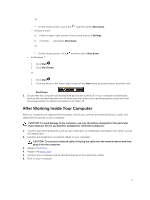
only perform troubleshooting and simple repairs as authorized in your product documentation, or as directed by the online or telephone service and support team. Damage due to servicing that is not authorized by Dell is not covered by your warranty. Read and follow the safety instructions that came - Dell Latitude E5450 | Dell LatitudeE5450 / 5450 Owners Manual - Page 4
3. If the computer is connected to a docking device (docked), undock it. CAUTION: To disconnect a network avoid damaging the system board, you must remove the main battery before you service the computer. 7. Remove the base cover. 8. Remove the main battery. 9. Turn the computer top-side up. 10. Open - Dell Latitude E5450 | Dell LatitudeE5450 / 5450 Owners Manual - Page 5
To avoid damage to the computer, use only the battery designed for this particular Dell computer. Do not use batteries designed for other Dell computers. 1. Connect any external devices, such as a port replicator or media base, and replace any cards, such as an ExpressCard. 2. Connect any telephone - Dell Latitude E5450 | Dell LatitudeE5450 / 5450 Owners Manual - Page 6
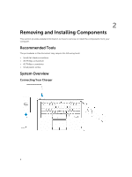
The procedures in this document may require the following tools: • Small flat-blade screwdriver • #0 Phillips screwdriver • #1 Phillips screwdriver • Small plastic scribe System Overview Connecting Your Charger 6 - Dell Latitude E5450 | Dell LatitudeE5450 / 5450 Owners Manual - Page 7
connectors 5. camera 7. HDMI connector 9. microphone 11. USB 3.0 connector with PowerShare 13. contactless smart-card reader (optional) 2. VGA connector 4. microphones (optional) 6. camera-status light 8. power connector 10. power button 12. memory-card reader 14. fingerprint reader (optional) 7 - Dell Latitude E5450 | Dell LatitudeE5450 / 5450 Owners Manual - Page 8
15. wireless-status light 17. hard-drive activity light 19. speakers 21. smart-card reader (optional) 23. security-cable slot 25. Service-Tag label 16. battery-status light 18. power-status light 20. touchpad 22. headset connector 24. dock connector (optional) Removing the SD Card 1. Follow the - Dell Latitude E5450 | Dell LatitudeE5450 / 5450 Owners Manual - Page 9
the procedures in After Working Inside Your Computer. Removing the Battery 1. Follow the procedures in Before Working Inside Your Computer. 2. Remove the base cover. 3. Disconnect the battery cable from its connector [1] and release the cable from its routing channel [2]. 4. Perform the following - Dell Latitude E5450 | Dell LatitudeE5450 / 5450 Owners Manual - Page 10
the procedures in After Working Inside Your Computer. Removing the Hard-Drive Assembly 1. Follow the procedure in Before Working Inside Your Computer. 2. Remove the: a. base cover b. battery 3. Perform the following steps: a. Disconnect the hard-drive cable from its connector on the system board - Dell Latitude E5450 | Dell LatitudeE5450 / 5450 Owners Manual - Page 11
4. Remove the hard-drive assembly from the computer. 5. Pull to release the hard-drive cable from its connector. 11 - Dell Latitude E5450 | Dell LatitudeE5450 / 5450 Owners Manual - Page 12
the hard-drive bracket to the hard drive [1] and remove the hard drive from the hard-drive bracket [2]. Installing the Hard-Drive Assembly 1. Place the hard-drive bracket on the hard drive to align the screw holders and tighten the screws to secure the hard-drive bracket. 2. Connect the hard-drive - Dell Latitude E5450 | Dell LatitudeE5450 / 5450 Owners Manual - Page 13
the: a. base cover b. battery 3. Pry the clips securing the memory module until the memory pops-up and remove the memory from the system board. Installing the Memory 1. Insert the memory on the memory socket until the clips secure the memory. 2. Install the: a. battery b. base cover 3. Follow the - Dell Latitude E5450 | Dell LatitudeE5450 / 5450 Owners Manual - Page 14
. Removing the Keyboard 1. Follow the procedures in Before Working Inside Your Computer. 2. Remove the: a. base cover b. battery c. keyboard trim 3. Disconnect the keyboard cable and touchpad cables from their connectors on the system board. 4. Remove the screws that secure the keyboard to the - Dell Latitude E5450 | Dell LatitudeE5450 / 5450 Owners Manual - Page 15
with the screw holders on the computer. 2. Connect the keyboard cable and touchpad cables to their connectors on the system board. 3. Tighten the screws to the keyboard to the computer. 4. Install the: a. keyboard trim b. battery c. base cover 5. Follow the procedures in After Working Inside Your - Dell Latitude E5450 | Dell LatitudeE5450 / 5450 Owners Manual - Page 16
. 4. Flip the computer and perform the following steps: a. Disconnect the following cables from its connectors on the system board [1] [2]: • LED board • touchpad board • USH board b. Pry the palmrest on its edges to release it from the computer [3] 5. Remove the palmrest from the computer. 16 - Dell Latitude E5450 | Dell LatitudeE5450 / 5450 Owners Manual - Page 17
in Before Working Inside Your Computer. 2. Remove the: a. base cover b. battery c. memory d. keyboard trim e. keyboard f. palmrest 3. Perform the following steps: a. Disconnect the SmartCard reader board cable from the USH board [1] [2]. b. Peel the cable to release from the adhesive [3]. 17 - Dell Latitude E5450 | Dell LatitudeE5450 / 5450 Owners Manual - Page 18
4. Release the SmartCard reader board. To release the SmartCard reader board: a. Remove the screws that secure the SmartCard-reader board to the palmrest [1]. b. Push the SmartCard-reader board to release it [2]. 5. Remove the SmartCard reader board from the palmrest. 18 - Dell Latitude E5450 | Dell LatitudeE5450 / 5450 Owners Manual - Page 19
reader board to the palmrest. 3. Fix the SmartCard-reader cable and connect the SmartCard-reader cable to its connector on the USH board. 4. Install the: a. palmrest b. keyboard c. keyboard trim d. battery 2. Remove the: a. base cover b. battery c. hard-drive assembly d. keyboard trim e. keyboard f. - Dell Latitude E5450 | Dell LatitudeE5450 / 5450 Owners Manual - Page 20
to the USH board. 4. Install the: a. palmrest b. keyboard c. keyboard trim d. hard-drive assembly e. battery f. base cover 5. Follow the procedures in After Working Inside Your Computer. Removing the Finger-Print Reader Board 1. Follow the procedures in Before Working Inside Your Computer. 2. Remove - Dell Latitude E5450 | Dell LatitudeE5450 / 5450 Owners Manual - Page 21
board. 3. Place the metal bracket on the finger-print reader board and tighten the screw to secure the finger- print reader board. 4. Install the: a. keyboard trim b. keyboard c. palmrest d. battery e. base cover 5. Follow the procedures in After Working Inside Your Computer. Removing the LED Board - Dell Latitude E5450 | Dell LatitudeE5450 / 5450 Owners Manual - Page 22
Working Inside Your Computer. Removing the Power-Connector Port 1. Follow the procedures in Before Working Inside Your Computer. 2. Remove the: a. base cover b. battery 3. Perform the following steps: a. Release the power-connector port cable from its routing channels [1]. b. Remove the screws to - Dell Latitude E5450 | Dell LatitudeE5450 / 5450 Owners Manual - Page 23
the power-connector port cable to its routing channels and connect the power-connector port cable to its connector on the system board. 4. Install the: a. battery b. base cover 5. Follow the procedures in After Working Inside Your Computer. 23 - Dell Latitude E5450 | Dell LatitudeE5450 / 5450 Owners Manual - Page 24
Removing the WLAN Card 1. Follow the procedures in Before Working Inside Your Computer. 2. Remove the base cover. 3. Perform the following steps to remove the WLAN card: a. Disconnect the WLAN cables from their connectors on the WLAN card [1]. b. Remove the screw that secures the WLAN card to the - Dell Latitude E5450 | Dell LatitudeE5450 / 5450 Owners Manual - Page 25
Removing the WWAN Card 1. Follow the procedures in Before Working Inside Your Computer. 2. Remove the base cover. 3. Disconnect the WWAN cables from their connectors on the WWAN card. 4. Remove the screw that secures the WWAN card [1] and remove the WWAN card from the computer [2]. Installing the - Dell Latitude E5450 | Dell LatitudeE5450 / 5450 Owners Manual - Page 26
Removing the Display-Hinge Brackets 1. Follow the procedures in Before Working Inside Your Computer. 2. Remove the: a. base cover b. battery c. memory d. hard-drive assembly e. keyboard trim f. keyboard g. palmrest 3. Remove the screws that secure the display-hinge brackets to the back of the - Dell Latitude E5450 | Dell LatitudeE5450 / 5450 Owners Manual - Page 27
Install the: a. palmrest b. keyboard c. keyboard trim d. hard-drive assembly e. memory f. battery g. base cover 4. Follow the procedures in After Working Inside steps to disconnect the display cable from the system board: a. Release the display cable from its routing channel [1]. b. Remove the screw - Dell Latitude E5450 | Dell LatitudeE5450 / 5450 Owners Manual - Page 28
5. Disconnect the display cable from its connector [1] and release the display cable [2]. 6. Remove the screws that secure the display assembly [1] and lift the display assembly to remove it from the computer [2]. 28 - Dell Latitude E5450 | Dell LatitudeE5450 / 5450 Owners Manual - Page 29
and tighten the screw to secure the display cable to the computer. 6. Install the: a. display-hinge brackets b. palmrest c. keyboard d. keyboard trim e. battery f. base cover 7. Follow the procedures in After Working Inside Your Computer. Removing the Display Bezel 1. Follow the procedures in Before - Dell Latitude E5450 | Dell LatitudeE5450 / 5450 Owners Manual - Page 30
Working Inside Your Computer. Removing the Display Panel 1. Follow the procedures in Before Working Inside Your Computer. 2. Remove the: a. base cover b. battery c. display bezel 3. Remove the screws that secure the display panel to the display assembly [1] and lift to flip the display panel to - Dell Latitude E5450 | Dell LatitudeE5450 / 5450 Owners Manual - Page 31
4. Peel the adhesive [1] to access the eDP cable [2]. 5. Disconnect the eDP cable from its connector [1] and remove the display panel from the display assembly [2]. 31 - Dell Latitude E5450 | Dell LatitudeE5450 / 5450 Owners Manual - Page 32
Removing the Display Hinges 1. Follow the procedures in Before Working Inside Your Computer. 2. Remove the: a. base cover b. battery c. memory d. hard-drive assembly e. keyboard trim f. keyboard g. palmrest h. display-hinge brackets i. display assembly j. display bezel 3. Perform the following steps - Dell Latitude E5450 | Dell LatitudeE5450 / 5450 Owners Manual - Page 33
hinge brackets d. palmrest e. keyboard f. keyboard trim g. hard-drive assembly h. memory i. battery j. base cover 4. Follow the procedures in After battery c. display bezel d. display panel 3. Perform the following steps to remove the camera from the computer: a. Lift the camera to release it - Dell Latitude E5450 | Dell LatitudeE5450 / 5450 Owners Manual - Page 34
. Removing the eDP Cable 1. Follow the procedures in Before Working Inside Your Computer. 2. Remove the: a. base cover b. battery c. memory d. hard-drive assembly e. keyboard trim f. keyboard g. palmrest h. display-hinge brackets i. display assembly j. display bezel k. display panel 3. Perform the - Dell Latitude E5450 | Dell LatitudeE5450 / 5450 Owners Manual - Page 35
to its connector. 3. Install the: a. display panel b. display bezel c. display assembly d. display-hinge brackets e. palmrest f. keyboard g. keyboard trim h. hard-drive assembly i. memory j. battery k. base cover 4. Follow the procedures in After Working Inside Your Computer. Removing the Coin-Cell - Dell Latitude E5450 | Dell LatitudeE5450 / 5450 Owners Manual - Page 36
to its connector on the system board. 3. Stick the adhesive tape to secure the coin-cell battery cable. 4. Install the: a. palmrest b. keyboard c. keyboard trim d. hard-drive assembly e. memory f. base cover 5. Follow the procedures in After Working Inside Your Computer. Removing the System Board - Dell Latitude E5450 | Dell LatitudeE5450 / 5450 Owners Manual - Page 37
j. display assembly 3. Disconnect the speaker cable [1] and release the speaker cable from its routing channels [2]. 4. Remove the screws that secure the system board to the chassis. 5. Remove the system board from the computer. 37 - Dell Latitude E5450 | Dell LatitudeE5450 / 5450 Owners Manual - Page 38
the cable through its routing channels. 4. Install the: a. display assembly b. display-hinge brackets c. palmrest d. keyboard e. keyboard trim f. hard-drive assembly g. memory h. battery i. base cover j. SD card 5. Follow the procedures in After Working Inside Your Computer. Removing the Heatsink - Dell Latitude E5450 | Dell LatitudeE5450 / 5450 Owners Manual - Page 39
g. WWAN h. keyboard lattice i. keyboard j. palmrest k. display-hinge brackets l. display assembly m. coin-cell battery n. system board 3. Disconnect the system-fan cable from its connector on the system board. 4. Perform the following steps: a. Remove the screws that secure the heatsink - Dell Latitude E5450 | Dell LatitudeE5450 / 5450 Owners Manual - Page 40
in Before Working Inside Your Computer. 2. Remove the: a. base cover b. battery c. memory d. hard-drive assembly e. keyboard trim f. keyboard g. palmrest 3. Disconnect the speaker cable from its connector on the system board [1] and release the speaker cables from their routing channels [2]. 40 - Dell Latitude E5450 | Dell LatitudeE5450 / 5450 Owners Manual - Page 41
the speaker cables through their routing channels. 4. Connect the speaker cable to its connector on the system board. 5. Install the: a. palmrest b. keyboard c. keyboard trim d. hard-drive assembly e. memory f. battery g. base cover 6. Follow the procedures in After Working Inside Your Computer. 41 - Dell Latitude E5450 | Dell LatitudeE5450 / 5450 Owners Manual - Page 42
• Device Information: Displays Primary Hard Drive, Dock eSATA Device, LOM MAC Address, Video Controller, Video BIOS Version, Video Memory, Panel Type, Native Resolution, Audio Controller, Wi-Fi Device, WiGig Device, Cellular Device, Bluetooth Device. Battery Information Boot Sequence Displays the - Dell Latitude E5450 | Dell LatitudeE5450 / 5450 Owners Manual - Page 43
you to configure the parallel port on the docking station. The options are: • Disabled • AT: This option is enabled by default hard-drive controller. The options are: • Disabled • AHCI • RAID On: This option is enabled by default. Drives Allows you to configure the SATA drives on board. All drives - Dell Latitude E5450 | Dell LatitudeE5450 / 5450 Owners Manual - Page 44
resume normal operation, press Fn+F7 again. This option is disabled by default. Allows you to enable or disable the following devices: • Enable Microphone • Enable Camera • Enable Hard Drive Free Fall Protection • Enable Media Card • Disable Media Card NOTE: All devices are enabled by default. You - Dell Latitude E5450 | Dell LatitudeE5450 / 5450 Owners Manual - Page 45
you to enable or disable the permission to bypass the System and the Internal HDD password, when they are set. The options are: • Disabled • Reboot bypass Default Setting: Disabled Allows you to enable the disable permission to the System and Hard Drive passwords when the admin password is set. 45 - Dell Latitude E5450 | Dell LatitudeE5450 / 5450 Owners Manual - Page 46
options are allowed when an Administrator Password is set. If disabled the setup options are locked by the admin password. Allows you to enable the Deactivate (default) CPU XD Support Allows you to enable the Execute Disable mode of the processor. Enable CPU XD Support (default) OROM Keyboard - Dell Latitude E5450 | Dell LatitudeE5450 / 5450 Owners Manual - Page 47
- Saves the key to a user-selected file • Replace from File- Replaces the current key with a key from a user- disable multi-core support for the processor. The installed processor supports two cores. If you enable Multi Core Support, two cores will be enabled. If you disable Multi Core Support - Dell Latitude E5450 | Dell LatitudeE5450 / 5450 Owners Manual - Page 48
remove power from all of the USB ports to conserve battery power. • Enable USB Wake Support Default Setting: The option is disabled. Allows you to enable or disable the feature that automatically switches from wired or wireless networks without depending on the physical connection. • Control WLAN - Dell Latitude E5450 | Dell LatitudeE5450 / 5450 Owners Manual - Page 49
Charge Stop. NOTE: All charging mode may not be available for all the batteries. To enable this option, disable the Advanced Battery Charge Configuration option. This option, if enabled, periodically senses the nearby wireless connections, while the system is in sleep state. You can use this option - Dell Latitude E5450 | Dell LatitudeE5450 / 5450 Owners Manual - Page 50
Enable Fn Key Emulation (default) Fn Lock Hot Key MEBx Hotkey Fastboot Extended BIOS POST Time Allows the hot key combination + toggle the seconds Table 9. Virtualization Support Option Description Virtualization Allows you to enable or disable the Intel Virtualization Technology. - Dell Latitude E5450 | Dell LatitudeE5450 / 5450 Owners Manual - Page 51
Device Enable Allows you to enable or disable the internal wireless devices. • WWAN / GPS • WLAN / WiGig • Bluetooth All the options are enabled by default. Table 11. Maintenance Option Service Tag Asset Tag Table 12. System Logs Option BIOS Events Thermal Events Power Events Description Displays - Dell Latitude E5450 | Dell LatitudeE5450 / 5450 Owners Manual - Page 52
. NOTE: In Windows 8.1, navigate to Help and Support to view information about your computer. Table 13. 14. Processor Feature Types L3 cache i3 i5 Specification Intel Celeron Core i3/ i5 2 MB 2 MB Table 15. Memory Feature Memory connector Memory capacity Memory type Minimum memory Maximum memory - Dell Latitude E5450 | Dell LatitudeE5450 / 5450 Owners Manual - Page 53
support Table 18. Camera Features Camera Resolution Video Resolution (maximum) Diagonal viewing angle Table 19. Communications Features Network adapter Wireless system board, hardware accelerated • Celeron Intel HD Graphics • i3, i5 Intel HD Graphics 4400 Integrated video • 19-pin HDMI connector • - Dell Latitude E5450 | Dell LatitudeE5450 / 5450 Owners Manual - Page 54
Video Network adapter USB Memory card reader Micro Subscriber Identity Module (uSIM) card Docking port Specification Stereo headset / mic combo • one 19-pin HDMI connector • one 15-pin DSUB VGA connector one RJ-45 connector Three USB 3.0, One USB BC v1.2 complaint connector supports up to SD4.0 one - Dell Latitude E5450 | Dell LatitudeE5450 / 5450 Owners Manual - Page 55
Kingdom: 107 keys, Brazil: 109 keys, and Japan: 110 keys Table 24. Touchpad Feature Active Area: X-axis Y-axis Specification 99.50 mm 53.00 mm Table 25. Battery Feature E5450 Type 3-Cell (38 WHr) 4-Cell (51 WHr) Dimensions: Depth 177.50 mm (6.98 inches) 233.00 mm (9.17 inches) Height - Dell Latitude E5450 | Dell LatitudeE5450 / 5450 Owners Manual - Page 56
Feature Input current (maximum) Input frequency Output current Rated output voltage Temperature range: Operating Non-Operating Specification 1.5 A 50 Hz to 60 Hz 3.34 A and 4.62 A 19.5 +/- 1.0 VDC 0 °C to 40 °C (32 °F to 104 °F) -40 °C to 70 °C (-40 °F to 158 °F) Feature W/O Touch Glass Fiber - Dell Latitude E5450 | Dell LatitudeE5450 / 5450 Owners Manual - Page 57
ePSA diagnostics before contacting Dell for technical assistance. The purpose of running diagnostics is to test your computer's hardware without requiring additional equipment or risking data loss. If you are unable to fix the problem yourself, service and support personnel can use the diagnostics - Dell Latitude E5450 | Dell LatitudeE5450 / 5450 Owners Manual - Page 58
Wireless LED Solid Solid Blinking Solid Off Blinking Blinking Fault Description A possible processor failure has occurred. The memory modules are detected but encountered an error. A system board failure has occurred. A possible graphics card/video failure has occurred. System failed on hard drive - Dell Latitude E5450 | Dell LatitudeE5450 / 5450 Owners Manual - Page 59
Off Power LED Solid Blinking Blinking Wireless LED Blinking Blinking Off Fault Description The display encountered a problem during initialization. The modem is preventing the system from completing POST Memory failed to initialize or memory is unsupported. Battery Status Lights If the computer - Dell Latitude E5450 | Dell LatitudeE5450 / 5450 Owners Manual - Page 60
options. Availability varies by country and product, and some services may not be available in your area. To contact Dell for sales, technical support, or customer service issues: 1. Go to dell.com/support. 2. Select your support category. 3. Verify your country or region in the Choose a Country
-
 1
1 -
 2
2 -
 3
3 -
 4
4 -
 5
5 -
 6
6 -
 7
7 -
8
-
9
-
10
-
11
-
12
-
13
-
14
-
15
-
16
-
17
-
18
-
19
-
20
-
21
-
22
-
23
-
24
-
25
-
26
-
27
-
28
-
29
-
30
-
31
-
32
-
33
-
34
-
35
-
36
-
37
-
38
-
39
-
40
-
41
-
42
-
43
-
44
-
45
-
46
-
47
-
48
-
49
-
50
-
51
-
52
-
53
-
54
-
55
-
56
-
57
-
58
-
59
-
60
 |
 |

Dell Latitude E5450 / 5450
Owner's Manual
Regulatory Model: P48G
Regulatory Type: P48G001