Dell Latitude E5450 Dell LatitudeE5450 / 5450 Owners Manual - Page 22
Installing the LED Board, Removing the Power-Connector Port, palmrest, keyboard, keyboard trim
 |
View all Dell Latitude E5450 manuals
Add to My Manuals
Save this manual to your list of manuals |
Page 22 highlights
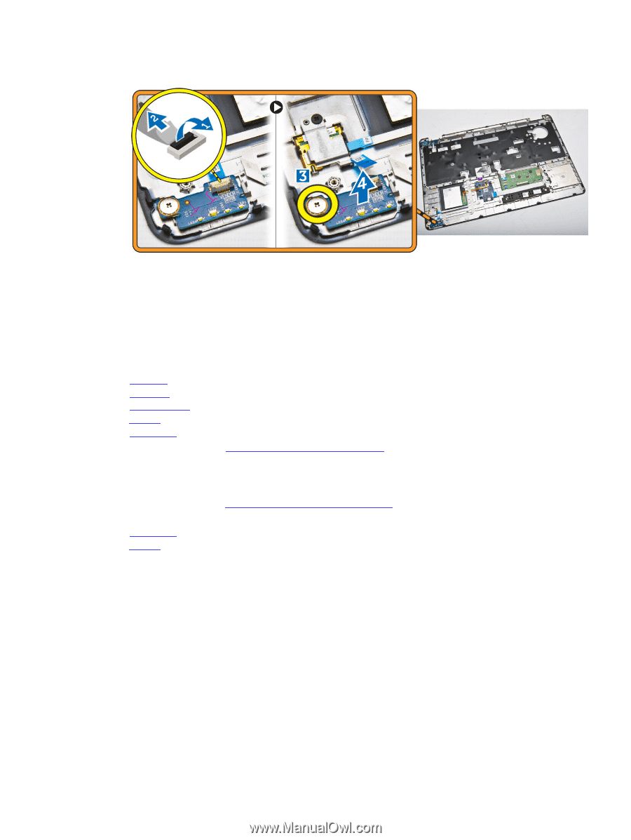
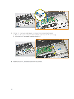
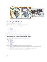
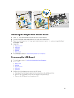
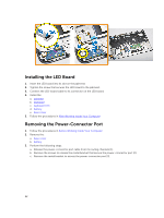
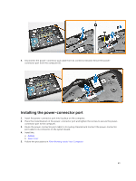
Installing the LED Board 1. Insert the LED board into its slot on the palmrest. 2. Tighten the screw that secures the LED board to the palmrest. 3. Connect the LED-board cable to its connector on the LED board. 4. Install the: a. palmrest b. keyboard c. keyboard trim d. battery e. base cover 5. Follow the procedures in After Working Inside Your Computer. Removing the Power-Connector Port 1. Follow the procedures in Before Working Inside Your Computer. 2. Remove the: a. base cover b. battery 3. Perform the following steps: a. Release the power-connector port cable from its routing channels [1]. b. Remove the screws to release the metal bracket that secure the power-connector port [2]. c. Remove the metal bracket to access the power-connector port [3]. 22
-
 1
1 -
2
-
3
-
4
-
5
-
6
-
7
-
8
-
9
-
10
-
11
-
12
-
13
-
14
-
15
-
16
-
 17
17 -
 18
18 -
 19
19 -
 20
20 -
 21
21 -
 22
22 -
 23
23 -
 24
24 -
 25
25 -
 26
26 -
 27
27 -
28
-
29
-
30
-
31
-
32
-
33
-
34
-
35
-
36
-
37
-
38
-
39
-
40
-
41
-
42
-
43
-
44
-
45
-
46
-
47
-
48
-
49
-
50
-
51
-
52
-
53
-
54
-
55
-
56
-
57
-
58
-
59
-
60
 |
 |