Dell OptiPlex 3010 Owners Manual - Page 27
Installing The Input/Output Panel, Removing The Power Supply
 |
View all Dell OptiPlex 3010 manuals
Add to My Manuals
Save this manual to your list of manuals |
Page 27 highlights
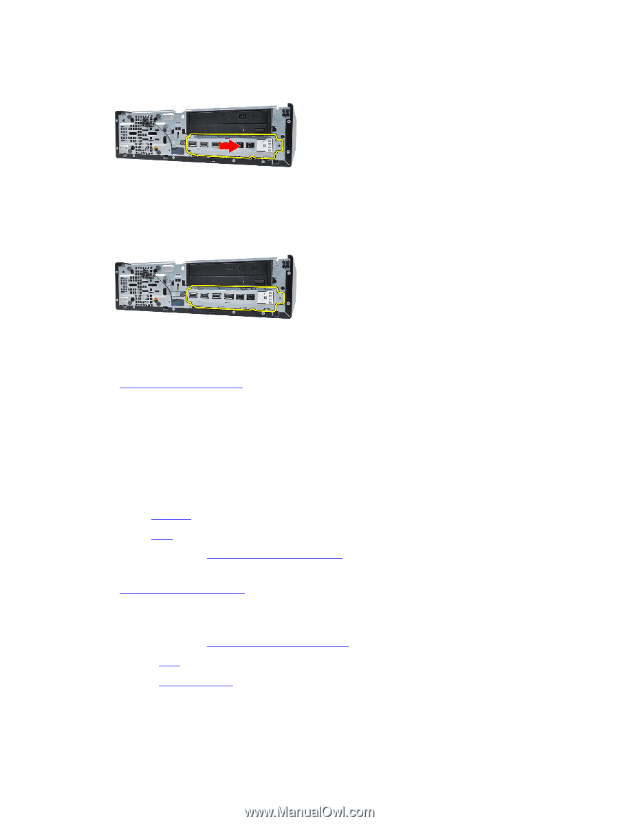
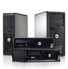
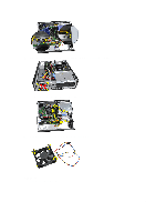
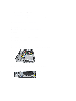
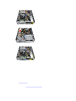
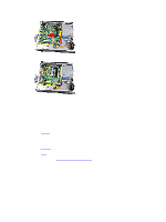
7. Remove the Input/Output panel. Related Links Installing The Input/Output Panel Installing The Input/Output Panel 1. Insert the Input/Output panel into the slot on the chassis front. 2. Slide the Input/Output panel towards the left of the computer to secure to the chassis. 3. Tighten the screw to secure the Input/Output panel to the chassis. 4. Connect the Input/Output panel or the FlyWire cable to the system board. 5. Install the front bezel. 6. Install the cover. 7. Follow the procedures in After Working Inside Your Computer. Related Links Removing The Input/Output Panel Removing The Power Supply 1. Follow the procedures in Before Working Inside Your Computer. 2. Remove the cover. 3. Remove the PSU thermal sensor. 4. Disconnect the 4-pin power cable from the system board. 27
-
 1
1 -
2
-
3
-
4
-
5
-
6
-
7
-
8
-
9
-
10
-
11
-
12
-
13
-
14
-
15
-
16
-
17
-
18
-
19
-
20
-
21
-
 22
22 -
 23
23 -
 24
24 -
 25
25 -
 26
26 -
 27
27 -
 28
28 -
 29
29 -
 30
30 -
 31
31 -
 32
32 -
33
-
34
-
35
-
36
-
37
-
38
-
39
-
40
-
41
-
42
-
43
-
44
-
45
-
46
-
47
-
48
-
49
-
50
-
51
-
52
-
53
-
54
-
55
-
56
-
57
-
58
-
59
-
60
-
61
-
62
-
63
 |
 |