Dell OptiPlex 5055 Tower OptiPlex 5055 Tower Owners Manual
Dell OptiPlex 5055 Tower Manual
 |
View all Dell OptiPlex 5055 Tower manuals
Add to My Manuals
Save this manual to your list of manuals |
Dell OptiPlex 5055 Tower manual content summary:
- Dell OptiPlex 5055 Tower | OptiPlex 5055 Tower Owners Manual - Page 1
Dell OptiPlex 5055 Tower Owner's Manual Regulatory Model: D18M Regulatory Type: D18M004 - Dell OptiPlex 5055 Tower | OptiPlex 5055 Tower Owners Manual - Page 2
data and tells you how to avoid the problem. WARNING: A WARNING indicates a potential for property damage, personal injury, or death. © 2018 2018 Dell Inc. or its subsidiaries. All rights reserved. Dell, EMC, and other trademarks are trademarks of Dell Inc. or its subsidiaries. Other trademarks may - Dell OptiPlex 5055 Tower | OptiPlex 5055 Tower Owners Manual - Page 3
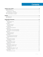
Contents 1 Working on your computer...6 Safety instructions...6 Turning off your computer...6 Turning off your - Windows...6 Before working inside your computer...7 After working inside your computer...7 2 Chassis...8 Front chassis view...8 Back chassis view ...9 3 - Dell OptiPlex 5055 Tower | OptiPlex 5055 Tower Owners Manual - Page 4
...42 Installing the system board...45 System board layout...46 4 Technology and components...49 Systems management features...49 In-Band Systems Management - Dell Client Command Suite 49 Out-of-Band Systems Management - DASH...50 AMD APUs, AMD Ryzen CPUs and APUs...50 AMD Advanced Processing Unit - Dell OptiPlex 5055 Tower | OptiPlex 5055 Tower Owners Manual - Page 5
64 Updating your system BIOS using a USB flash drive 64 Updating the Dell BIOS in Linux and Ubuntu environments 64 Flashing the BIOS from the F12 71 Controls and lights ...72 Power...72 Physical dimension...73 Environmental...73 8 Troubleshooting...74 Diagnostic and Power LED codes...74 Enhanced - Dell OptiPlex 5055 Tower | OptiPlex 5055 Tower Owners Manual - Page 6
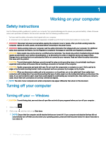
only perform troubleshooting and simple repairs as authorized in your product documentation, or as directed by the online or telephone service and support team. Damage due to servicing that is not authorized by Dell is not covered by your warranty. Read and follow the safety instructions that came - Dell OptiPlex 5055 Tower | OptiPlex 5055 Tower Owners Manual - Page 7
To avoid damaging your computer, perform the following steps before you begin working inside the computer. 1 Ensure that you follow the Safety Instruction. 2 Ensure that your work surface is flat and clean to prevent the computer cover from being scratched. 3 Turn off your computer. 4 Disconnect - Dell OptiPlex 5055 Tower | OptiPlex 5055 Tower Owners Manual - Page 8
Front chassis view 2 Chassis 1 Power button and power light 3 Memory card reader (optional) 5 Headset port 7 USB 2.0 port 2 Hard drive activity light 4 Optical drive (optional) 6 USB 2.0 port with PowerShare 8 USB 3.1 Gen1 port 8 Chassis - Dell OptiPlex 5055 Tower | OptiPlex 5055 Tower Owners Manual - Page 9
Power supply diagnostic light 11 Kensington security cable slot 13 PS/2 mouse port 15 Release latch 2 DisplayPort 4 PS/2 keyboard port 6 USB 2.0 ports (supports Smart Power On) 8 Power connector port 10 Padlock ring 12 Network port 14 VGA connector port (optional) 16 Cable cover lock slot Chassis - Dell OptiPlex 5055 Tower | OptiPlex 5055 Tower Owners Manual - Page 10
Back cover 3 Disassembly and reassembly Removing Back Cover 1 Follow the procedure in Before working inside your computer. 2 To release back cover: a Slide the latch (blue tab) to release the back cover from the computer [1]. b Slide the back cover toward the back of the computer [2]. 3 Lift the - Dell OptiPlex 5055 Tower | OptiPlex 5055 Tower Owners Manual - Page 11
Installing cover 1 Place the cover on the computer and slide the cover forward until it clicks into place. 2 Follow the procedure in After working inside your computer. Front Bezel Removing front bezel 1 Follow the procedure in Before working inside your computer. 2 Remove the Back cover. 3 To - Dell OptiPlex 5055 Tower | OptiPlex 5055 Tower Owners Manual - Page 12
4 Lift the front bezel to remove it from the computer. 12 Disassembly and reassembly - Dell OptiPlex 5055 Tower | OptiPlex 5055 Tower Owners Manual - Page 13
Installing front bezel 1 Position the bezel to align with the tab holders on the base of the chassis frame. 2 Press the bezel until the retention tabs click into place. 3 Install the Back cover. 4 Follow the procedure in After working inside your computer. Front panel door Opening the front panel - Dell OptiPlex 5055 Tower | OptiPlex 5055 Tower Owners Manual - Page 14
Storage device Removing 3.5-inch hard drive assembly 1 Follow the procedure in Before working inside your computer. 2 Remove the: a Back cover b Front bezel 3 To remove hard drive assembly: a Disconnect the hard drive assembly cables from the connectors on the hard drive. 14 Disassembly and - Dell OptiPlex 5055 Tower | OptiPlex 5055 Tower Owners Manual - Page 15
NOTE: Un-route the cables from the clips from the drive cage. b Open the front panel door. c Remove the HDD filler bracket. Disassembly and reassembly 15 - Dell OptiPlex 5055 Tower | OptiPlex 5055 Tower Owners Manual - Page 16
d Press the blue tab [1] and pull the hard drive assembly out of the computer [2]. 16 Disassembly and reassembly - Dell OptiPlex 5055 Tower | OptiPlex 5055 Tower Owners Manual - Page 17
NOTE: The tab may indicate 5.25 inch because you can also install a 5.25 inch hard drive in same drive bay. Removing 3.5-inch hard drive from the hard drive bracket 1 Follow the procedure in Before working inside your computer. 2 Remove the: a Back cover b Front bezel c Hard drive assembly 3 To - Dell OptiPlex 5055 Tower | OptiPlex 5055 Tower Owners Manual - Page 18
Installing 3.5-inch hard drive into the hard drive bracket 1 Flex the side of the hard drive bracket, to align and insert the pins on the bracket into the hard drive. 2 Insert the hard drive into the hard drive bracket until it clicks into place. 3 Install the: a Hard drive assembly b Front bezel c - Dell OptiPlex 5055 Tower | OptiPlex 5055 Tower Owners Manual - Page 19
Removing 2.5-inch hard drive from the hard drive bracket 1 Follow the procedure in Before working inside your computer. 2 Remove the: a Back cover b Front bezel c 2.5 inch hard drive assembly 3 To remove hard drive bracket: a Pull one side of the hard drive bracket to disengage the pins on the - Dell OptiPlex 5055 Tower | OptiPlex 5055 Tower Owners Manual - Page 20
Installing 2.5-inch hard drive into the hard drive bracket 1 Flex the side of the hard drive bracket, to align and insert the pins on the bracket into the hard drive. 2 Insert the hard drive into the hard drive bracket until it clicks into place. 3 Install the: a 2.5 inch hard drive assembly b Front - Dell OptiPlex 5055 Tower | OptiPlex 5055 Tower Owners Manual - Page 21
c Press the blue release tab [1] and slide the optical drive out of the computer [2]. Disassembly and reassembly 21 - Dell OptiPlex 5055 Tower | OptiPlex 5055 Tower Owners Manual - Page 22
Installing optical drive 1 Insert the optical drive into the optical drive bay until it clicks into place. 2 Open the Front panel door. 3 Route the data cable and power cable under the drive cage. 4 Connect the data cable and power cable to the connectors on the optical drive. 5 Close the front - Dell OptiPlex 5055 Tower | OptiPlex 5055 Tower Owners Manual - Page 23
3 Open the Front panel door. 4 To remove the M.2 PCIe SSD: a Pull the blue plastic tab that secures the M.2 PCIe SSD to the system board [1]. b Slide the M.2 PCIe SSD from the connector on the system board [2]. Installing optional M.2 PCIe SSD 1 Insert the M.2 PCIe SSD to the connector. 2 Press the - Dell OptiPlex 5055 Tower | OptiPlex 5055 Tower Owners Manual - Page 24
SD card Removing SD card reader 1 Follow the procedure in Before working inside your computer. 2 Remove the: a Back cover b Front bezel 3 Open the Front panel door. 4 To remove the SD card reader: a Disconnect the SD card reader cable from the connector on the system board [1]. b Remove the screw( - Dell OptiPlex 5055 Tower | OptiPlex 5055 Tower Owners Manual - Page 25
FInstalling SD card reader 1 Insert the SD card reader into the slot on the system board. 2 Replace the screw(6+/-1) to secure the SD card reader to the front panel door. NOTE: The screw holder is beneath the SD card reader. 3 Connect the SD card reader cable to the connector on the system board. 4 - Dell OptiPlex 5055 Tower | OptiPlex 5055 Tower Owners Manual - Page 26
Expansion card Removing PCIe expansion card 1 Follow the procedure in Before working inside your computer. 2 Remove the: a Back cover b Front bezel 3 Remove the Front panel door. 4 To remove the PCIe expansion card: a Pull the release latch to unlock the PCIe expansion card [1]. b Push the release - Dell OptiPlex 5055 Tower | OptiPlex 5055 Tower Owners Manual - Page 27
NOTE: To remove the PCIe brackets (2 and 4), push the bracket upwards from the inside of your computer to release it and then lift the bracket away from your computer. 7 Repeat the steps to remove any additional PCIe expansion cards. Installing PCIe expansion card 1 Insert the PCIe expansion card to - Dell OptiPlex 5055 Tower | OptiPlex 5055 Tower Owners Manual - Page 28
5 To remove the PSU: a Press the release tab [1]. NOTE: Release tab is at the base of the PSU b Slide and lift the PSU away from the computer [2]. 28 Disassembly and reassembly - Dell OptiPlex 5055 Tower | OptiPlex 5055 Tower Owners Manual - Page 29
Installing power supply unit - PSU 1 Insert the PSU into the PSU slot and slide it toward the back of the computer until it clicks into place. 2 Replace the screws( 6+/-1) to secure the PSU to the computer. 3 Route the PSU cables through the retention clips. 4 Connect the PSU cables to the - Dell OptiPlex 5055 Tower | OptiPlex 5055 Tower Owners Manual - Page 30
Removing intrusion switch 1 Follow the procedure in Before working inside your computer. 2 Remove the: a Back cover b Front bezel 3 Open the Front panel door. 4 To the intrusion switch: a Disconnect the intrusion switch cable from the connector on the system board [1]. b Un-route the intrusion - Dell OptiPlex 5055 Tower | OptiPlex 5055 Tower Owners Manual - Page 31
5 Install the: a Front bezel b Back cover 6 Follow the procedure in After working inside your computer. Power switch Removing power switch 1 Follow the procedure in Before working inside your computer. 2 Remove the: a Back cover b Front bezel 3 Open the Front panel door. 4 To release the power - Dell OptiPlex 5055 Tower | OptiPlex 5055 Tower Owners Manual - Page 32
Installing power switch 1 Insert the power switch into the slot from the front of the computer and press it until it clicks into place. 2 Align the cable with the pins on the connector and connect the cable. 3 Close the front panel door. 4 Install the: a Front bezel b Back cover 5 Follow the - Dell OptiPlex 5055 Tower | OptiPlex 5055 Tower Owners Manual - Page 33
4 To remove the speaker: a Disconnect the speaker cable from the connector on the system board [1]. b Close the front panel door [2]. c Press the release tabs [1], and slide the speaker module [2] out of the slot. Disassembly and reassembly 33 - Dell OptiPlex 5055 Tower | OptiPlex 5055 Tower Owners Manual - Page 34
Installing speaker 1 Insert the speaker into the slot. 2 Press the speaker module until it clicks into place. 3 Connect the speaker cable to the connector on the system board. 4 Close the front panel door. 5 Install the: a Front bezel b Back cover 6 Follow the procedure in After working inside your - Dell OptiPlex 5055 Tower | OptiPlex 5055 Tower Owners Manual - Page 35
c Expansion card 3 Open the Front panel door. 4 To remove the coin cell battery: a Using a plastic scribe press the release latch until the coin cell battery pops out [1]. b Remove the coin cell battery from the connector on the system board [2]. Installing coin cell battery 1 Hold the coin cell - Dell OptiPlex 5055 Tower | OptiPlex 5055 Tower Owners Manual - Page 36
Heat sink assembly Removing heat sink assembly 1 Follow the procedure in Before working inside your computer. 2 Remove the: a Back cover b Front bezel 3 Open the Front panel door. 4 To remove the heat sink assembly: a Disconnect the heat sink assembly cable from the connector on the system board - Dell OptiPlex 5055 Tower | OptiPlex 5055 Tower Owners Manual - Page 37
Installing heat sink assembly 1 Align the screws of the heat sink assembly with the holders on the system board. 2 Place the heat sink assembly on the processor. 3 Replace the captive screws (6+/-1) to secure the heat sink assembly to the system board. NOTE: Tighten the screws based on the order - Dell OptiPlex 5055 Tower | OptiPlex 5055 Tower Owners Manual - Page 38
Installing the processor 1 Align the processor with the socket keys. CAUTION: Do not use force to seat the processor. When the processor is positioned correctly, it engages easily into the socket. 2 Align the pin-1 indicator of the processor with the triangle on the socket. 3 Place the processor on - Dell OptiPlex 5055 Tower | OptiPlex 5055 Tower Owners Manual - Page 39
System fan Removing the system fan 1 Follow the procedure in Before working inside your computer. 2 Remove the: a Back cover b Front bezel 3 Open the Front panel door. 4 To remove the system fan: a Disconnect the system fan cable from the connector on the system board [1]. b Remove the tape that - Dell OptiPlex 5055 Tower | OptiPlex 5055 Tower Owners Manual - Page 40
Installing the system fan 1 Insert the grommets into the slots on the chassis frame. 2 Hold the system fan with the cable facing the base of the computer. 3 Align the grooves of the system fan with the grommets on the chassis wall. 4 Pass the grommets through the corresponding grooves on the system - Dell OptiPlex 5055 Tower | OptiPlex 5055 Tower Owners Manual - Page 41
Installing the VGA daughter board 1 Align the VGA daughter board with the screw holder on the system board. 2 Tighten the screw to secure the VGA daughter board to the system board. 3 Insert the VGA connector into the slot at the back of the computer. 4 Tighten the screws to secure the VGA connector - Dell OptiPlex 5055 Tower | OptiPlex 5055 Tower Owners Manual - Page 42
System board Removing the system board 1 Follow the procedure in Before working inside your computer. 2 Remove the: a Back cover b Front bezel 3 Open the front panel door. 4 Remove the: a Heat sink assembly b Processor c Expansion card d Optional M.2 PCIe SSD card e SD card reader f Memory module 5 - Dell OptiPlex 5055 Tower | OptiPlex 5055 Tower Owners Manual - Page 43
b power switch [2] c speaker [3] d PSU [4] e power distribution for optical drive and hard drive [5] f system fan [6] g intrusion switch [7] 7 To remove the system board: a Remove the screws (6+/-1) that secure the system board to the computer Disassembly and reassembly 43 - Dell OptiPlex 5055 Tower | OptiPlex 5055 Tower Owners Manual - Page 44
b Slide and lift the system board away from the computer [2]. 44 Disassembly and reassembly - Dell OptiPlex 5055 Tower | OptiPlex 5055 Tower Owners Manual - Page 45
Installing the system board 1 Hold the system board by its edges and align it toward the back of the computer. 2 Lower the system board into the chassis until the connectors at the back of the system board align with the slots on the chassis, and the screw holes on the system board align with the - Dell OptiPlex 5055 Tower | OptiPlex 5055 Tower Owners Manual - Page 46
7 Connect the system fan cable to the connector on the system board. 8 Close the front panel door. 9 Install the: a Memory module b Optional M.2 PCIe SSD c Expansion card d SD card reader e Processor f Heat sink assembly 10 Close the front panel door. a Back cover 11 Follow the procedure in After - Dell OptiPlex 5055 Tower | OptiPlex 5055 Tower Owners Manual - Page 47
Cable Connector (SATA_PWR) 2 PCI-e x4 Connector (SLOT1) - open ended X4 to support X16 4 Processor Socket (CPU) 6 Intrusion Switch Connector (INTRUDER) 8 Memory Slots ( Jumper (PASSWORD_CLR); Clear Password ; Jumper (PASSWORD_CLR); Service Mode Jumper (SERVICE_MODE) Disassembly and reassembly 47 - Dell OptiPlex 5055 Tower | OptiPlex 5055 Tower Owners Manual - Page 48
19 Internal Speaker Connector (INT_SPKR) 21 SATA 1 Connector White Color (SATA1) 20 Internal USB Connector (WF_BT_USB) 22 Battery Connector (BATTERY) 48 Disassembly and reassembly - Dell OptiPlex 5055 Tower | OptiPlex 5055 Tower Owners Manual - Page 49
able to manage the system in that state. In-Band Systems Management - Dell Client Command Suite The Dell Client Command Suite of tools is free to download at http://dell.com/command and can be used with all OptiPlex desktops. It contains the following components that can be used individually, or in - Dell OptiPlex 5055 Tower | OptiPlex 5055 Tower Owners Manual - Page 50
by the operating system. Dell Command | Integration Suite services management for desktop and mobile client systems. Through DASH, DMTF provides the next generation of standards for secure out-of-band and remote management of desktop and mobile systems. OptiPlex 5055 with DASH 1.2 on BCM5762 supports - Dell OptiPlex 5055 Tower | OptiPlex 5055 Tower Owners Manual - Page 51
• Performance: Simultaneous multithreading (SMT) to allow execution of two threads per core, increasing the Instruction Per Cycle(IPC) thus enhancing the processing throughput. • Power: AMD's Sense MI technology employs sensors across the chip to dynamically scaling the frequency and voltage - Dell OptiPlex 5055 Tower | OptiPlex 5055 Tower Owners Manual - Page 52
Table 2. Key Specifications Specification Product Line API Supported Clock Speed Bus Width Memory Clock Speed Technology Max External Resolution Interface Type AMD Radeon R7 M450 AMD DirectX 12 , OpenCL 1.2 , OpenGL 4.3 925 MHz 128- - Dell OptiPlex 5055 Tower | OptiPlex 5055 Tower Owners Manual - Page 53
bus power and increased device current draw to better accommodate power-hungry devices • New power management features • Full-duplex data transfers and support for new transfer types • Backward USB 2.0 compatibility • New connectors and cable The topics below cover some of the most commonly asked - Dell OptiPlex 5055 Tower | OptiPlex 5055 Tower Owners Manual - Page 54
present on USB 3.1 Gen 1 cables and only come into contact when connected to a proper SuperSpeed USB connection. Windows 8/10 will be bringing native support for USB 3.1 Gen 1 controllers. This is in contrast to previous versions of Windows, which continue to require separate drivers for USB 3.1 Gen - Dell OptiPlex 5055 Tower | OptiPlex 5055 Tower Owners Manual - Page 55
, perhaps not on its immediate release, but in a subsequent Service Pack or update. It is not out of the question to think that following a successful release of USB 3.1 Gen 1 support in Windows 7, SuperSpeed support would trickle down to Vista. Microsoft has confirmed this by stating that most - Dell OptiPlex 5055 Tower | OptiPlex 5055 Tower Owners Manual - Page 56
on the system display the new ON-FLASH-FLASH or ON-FLASH-ON failure code. If all memory fails, the LCD does not turn on. Troubleshoot for possible memory failure by trying known good memory modules in the memory connectors on the bottom of the system or under the keyboard, as - Dell OptiPlex 5055 Tower | OptiPlex 5055 Tower Owners Manual - Page 57
BIOS in Linux and Ubuntu environments • Flashing the BIOS from the F12 One-Time boot menu • Technical Specifications Boot menu Press when the Dell™ logo appears to initiate a one-time boot menu with a list of the valid boot devices for the system. Diagnostics and BIOS Setup options are also - Dell OptiPlex 5055 Tower | OptiPlex 5055 Tower Owners Manual - Page 58
Mode Date/Time Description Displays the following information: • System Information: Displays BIOS Version, Service Tag, Asset Tag, Ownership Tag, Ownership Date, Manufacture Date, Express Service Code and the Singed Firmware Update. • Memory Information: Displays Memory Installed, Memory Available - Dell OptiPlex 5055 Tower | OptiPlex 5055 Tower Owners Manual - Page 59
system startup. The Enable Smart Reporting option is disabled by default. Allows you to enable or disable the integrated USB controller for: • Enable Boot Support • Enable Front USB Ports • Enable Rear USB Ports All the options are enabled by default. This option allows you to charge the external - Dell OptiPlex 5055 Tower | OptiPlex 5055 Tower Owners Manual - Page 60
UEFI capsule update packages. This option is selected by default. Disabling this option will block BIOS updates from services such as Microsoft Windows Update and Linux Vendor Firmware Service (LVFS) Allows you to control whether the Trusted Platform Module (TPM) is visible to the operating system - Dell OptiPlex 5055 Tower | OptiPlex 5055 Tower Owners Manual - Page 61
Option Expert key Management Description • Disable (selected by default) • Enable Allows you to manipulate the security key databases only if the system is in Custom Mode. The Enable Custom Mode option is disabled by default. The options are: • PK (default) • KEK • db • dbx If you enable the Custom - Dell OptiPlex 5055 Tower | OptiPlex 5055 Tower Owners Manual - Page 62
to wake the computer from standby mode. The option "Enable USB Wake Support" is selected by default This option allows the computer to power up from enabled by default. Table 14. Maintenance Option Service Tag Asset Tag Description Displays the Service Tag of your computer. Allows you to create - Dell OptiPlex 5055 Tower | OptiPlex 5055 Tower Owners Manual - Page 63
the system BIOS, and then re-enabled after the BIOS update is completed. 1 Restart the computer. 2 Go to Dell.com/support. • Enter the Service Tag or Express Service Code and click Submit. • Click Detect Product and follow the instructions on screen. 3 If you are unable to detect or find the - Dell OptiPlex 5055 Tower | OptiPlex 5055 Tower Owners Manual - Page 64
more information on this subject, see Knowledge Article: http://www.dell.com/support/article/sln153694 Updating your system BIOS using a USB flash Update Utility will load, follow the instructions on screen. Figure 4. DOS BIOS Update Screen Updating the Dell BIOS in Linux and Ubuntu environments If - Dell OptiPlex 5055 Tower | OptiPlex 5055 Tower Owners Manual - Page 65
will need: • USB key formatted to the FAT32 file system (key does not have to be bootable) • BIOS executable file that you downloaded from the Dell Support website and copied to the root of the USB key • AC power adapter connected to the system • Functional system battery to flash the BIOS Perform - Dell OptiPlex 5055 Tower | OptiPlex 5055 Tower Owners Manual - Page 66
4 The E5450A14.exe file is shown as an example in the following screenshot. The actual file name may vary. 5 Once the file is selected, it will show in the file selection box and you can click the OK button to continue. 66 System setup - Dell OptiPlex 5055 Tower | OptiPlex 5055 Tower Owners Manual - Page 67
6 Click the Begin Flash Update button. 7 A warning box is displayed asking you if you want to proceed. Click the Yes button to begin the flash. System setup 67 - Dell OptiPlex 5055 Tower | OptiPlex 5055 Tower Owners Manual - Page 68
8 At this point the BIOS flash will execute, the system will reboot and then the BIOS flash will start and a progress bar will show the progress of the flash. Depending on the changes included in the update, the progress bar may go from zero to 100 multiple times and the flash process could take as - Dell OptiPlex 5055 Tower | OptiPlex 5055 Tower Owners Manual - Page 69
R7 PRO A6-9500 (DC/ L2 Cache: 1 MB/3.5 GHz/65 W) Up to 4MB NOTE: Extended Frequency (XFR) in GHz are not supported on OptiPlex 5055. Memory Table 19. Memory Specifications Feature Memory type Memory speed Memory connectors Memory capacity Minimum memory Maximum memory Specification DDR4 Up to - Dell OptiPlex 5055 Tower | OptiPlex 5055 Tower Owners Manual - Page 70
2x2 • Intel Wireless-AC 3165 1x1 • Bluetooth 4.1 NOTE: For optimal performance, it is recommended to use the wireless display feature with an access point that supports 5 GHz standard. - Dell OptiPlex 5055 Tower | OptiPlex 5055 Tower Owners Manual - Page 71
via external graphics cards • 15-pin VGA connector (one optional VGA connector only supports A- Series APU and Ryzen APUs) • Two DisplayPort 1.2 (DP only supported with A-Series APU and Ryzen APUs) NOTE: Available video connectors may vary based on the optional graphic board selected. System - Dell OptiPlex 5055 Tower | OptiPlex 5055 Tower Owners Manual - Page 72
Controls and lights Table 27. Controls and lights Feature Specification Front of the computer Power button light White light - Solid white light indicates power-on state; slow blinking white light indicates sleep state of the computer. Drive activity light White light - Slow blinking white - Dell OptiPlex 5055 Tower | OptiPlex 5055 Tower Owners Manual - Page 73
Table 29. Physical dimensions Physical Height Width Depth Weight Environmental Table Maximum vibration Operating Non-Operating Maximum shock Operating Non-Operating Altitude Operating Non-Operating Airborne contaminant level Tower 35 cm (13.8 inches) 15.4 cm(6.1 inches) 27.4 cm (10.8 inches) 7.93 - Dell OptiPlex 5055 Tower | OptiPlex 5055 Tower Owners Manual - Page 74
Table 31. Power LED states Power LED light status Off Steady/blinking amber Slow Blinking white light Steady white Possible cause Troubleshooting steps The computer is either turned • off or is not receiving power or in Hibernation mode. • • Re-seat the power cable in the power connector - Dell OptiPlex 5055 Tower | OptiPlex 5055 Tower Owners Manual - Page 75
> 1 blink > long pause > repeats Problem Description Bad Motherboard Suggested Resolution Replace the motherboard 2 blinks > short pause > 2 blinks > long pause > repeats Bad Motherboard, Power Supply or Power Supply cabling If customer can assist to troubleshoot, narrow down the issue with PSU - Dell OptiPlex 5055 Tower | OptiPlex 5055 Tower Owners Manual - Page 76
State S4 S5 S6 State Name PCI VID STO Blinking Amber Pattern Problem Description Suggested Resolution If customer can assist to troubleshoot, narrow down the issue with reseating memory and swapping a known good memory if available. If nothing works, replace the memory. 3 blinks > short pause > - Dell OptiPlex 5055 Tower | OptiPlex 5055 Tower Owners Manual - Page 77
S7 S8 S9 State Name USB MEM MBF Blinking Amber Pattern Problem Description Suggested Resolution If none of the memory failed, replace the in progress or storage subsystem failure. If customer can assist to troubleshoot, narrow down the issue by removing one by one storages on motherboard - Dell OptiPlex 5055 Tower | OptiPlex 5055 Tower Owners Manual - Page 78
be incompatible or in an invalid configuration. If customer can assist to troubleshoot, narrow down the issue by removing one by one the memory are completed successfully • View error messages that inform you of problems encountered during testing You can invoke the ePSA diagnostics by tapping F12 - Dell OptiPlex 5055 Tower | OptiPlex 5055 Tower Owners Manual - Page 79
options. Availability varies by country and product, and some services may not be available in your area. To contact Dell for sales, technical support, or customer service issues: 1 Go to Dell.com/support. 2 Select your support category. 3 Verify your country or region in the Choose a Country - Dell OptiPlex 5055 Tower | OptiPlex 5055 Tower Owners Manual - Page 80
8 Troubleshooting 80 Troubleshooting
-
 1
1 -
 2
2 -
 3
3 -
 4
4 -
 5
5 -
 6
6 -
 7
7 -
8
-
9
-
10
-
11
-
12
-
13
-
14
-
15
-
16
-
17
-
18
-
19
-
20
-
21
-
22
-
23
-
24
-
25
-
26
-
27
-
28
-
29
-
30
-
31
-
32
-
33
-
34
-
35
-
36
-
37
-
38
-
39
-
40
-
41
-
42
-
43
-
44
-
45
-
46
-
47
-
48
-
49
-
50
-
51
-
52
-
53
-
54
-
55
-
56
-
57
-
58
-
59
-
60
-
61
-
62
-
63
-
64
-
65
-
66
-
67
-
68
-
69
-
70
-
71
-
72
-
73
-
74
-
75
-
76
-
77
-
78
-
79
-
80
 |
 |

Dell OptiPlex 5055 Tower
Owner's Manual
Regulatory Model: D18M
Regulatory Type: D18M004