Dell OptiPlex 7080 Tower Service Manual
Dell OptiPlex 7080 Tower Manual
 |
View all Dell OptiPlex 7080 Tower manuals
Add to My Manuals
Save this manual to your list of manuals |
Dell OptiPlex 7080 Tower manual content summary:
- Dell OptiPlex 7080 Tower | Service Manual - Page 1
OptiPlex 7080 Tower Service Manual Regulatory Model: D28M Regulatory Type: D28M004 September 2021 Rev. A01 - Dell OptiPlex 7080 Tower | Service Manual - Page 2
data and tells you how to avoid the problem. WARNING: A WARNING indicates a potential for property damage, personal injury, or death. © 2020-2021 Dell Inc. or its subsidiaries. All rights reserved. Dell, EMC, and other trademarks are trademarks of Dell Inc. or its subsidiaries. Other trademarks may - Dell OptiPlex 7080 Tower | Service Manual - Page 3
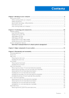
Contents Chapter 1: Working on your computer 6 Safety instructions...6 Before working inside your computer...6 Safety precautions...7 Electrostatic discharge-ESD protection...7 ESD field service kit ...8 After working inside your computer...9 Chapter 2: Technology and components 10 Graphics - Dell OptiPlex 7080 Tower | Service Manual - Page 4
heat sink...63 Removing the VR heat sink...63 Installing the VR heat sink...64 Speaker...65 Removing the speaker...65 Installing the speaker...66 Power button...67 Removing the power button...67 Installing the power button...68 Power-supply unit...69 4 Contents - Dell OptiPlex 7080 Tower | Service Manual - Page 5
Removing the system board...85 Installing the system board...88 Chapter 5: Troubleshooting...93 Dell SupportAssist Pre-boot System Performance Check diagnostics 93 Running the SupportAssist Pre-Boot System Performance Check 93 Power-Supply Unit Built-in Self-Test ...93 Diagnostic LED behavior...94 - Dell OptiPlex 7080 Tower | Service Manual - Page 6
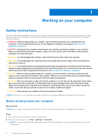
and the contacts. CAUTION: You should only perform troubleshooting and repairs as authorized or directed by the Dell technical assistance team. Damage due to servicing that is not authorized by Dell is not covered by your warranty. See the safety instructions that is shipped with the product or at - Dell OptiPlex 7080 Tower | Service Manual - Page 7
. ● Disconnect the system and all attached peripherals from AC power. ● Disconnect all network cables, telephone, and telecommunications lines from the system. ● Use an ESD field service kit when working inside any desktop to avoid electrostatic discharge (ESD) damage. ● After removing any - Dell OptiPlex 7080 Tower | Service Manual - Page 8
service Field Service kits to each service call, Service desktop or portable environment. Servers are typically installed in a rack within a data center; desktops Dell service technicians use the traditional wired ESD grounding wrist strap and protective anti-static mat at all times when servicing Dell - Dell OptiPlex 7080 Tower | Service Manual - Page 9
2. Connect any external devices, peripherals, or cables you removed before working on your computer. 3. Replace any media cards, discs, or any other parts that you removed before working on your computer. 4. Connect your computer and all attached devices to their electrical outlets. 5. Turn on your - Dell OptiPlex 7080 Tower | Service Manual - Page 10
USB type-C Alt mode: 4096 x 2304 @60 Hz ● Option VGA: 1920 x 1200 @60 Hz ● Option HDMI2.0: 4096 x 2160 @60 Hz Up to three displays supported ● Two motherboard integrated DP1.4 HBR2 + One video option (VGA/DP1.4 HBR2/HDMI2.0/USB3.2 Gen2 type-C Alt-mode) Two MB integrated DP1.4 HBR2 + One video option - Dell OptiPlex 7080 Tower | Service Manual - Page 11
PCB form factor Low profile PCB layer 4 layer PCB solder mask Green Bracket form factor Low profile Maximum resolution 3840 x 2160 Power support Graphics memory configuration Graphics memory clock speed Active fan sink Values 1.2 GHz 12 5.0 2.0 4.5 128 bit PCIe 3.0 x8 ● Two Mini - Dell OptiPlex 7080 Tower | Service Manual - Page 12
Bracket form factor Low profile Maximum resolution 5120 x 2880 Power consumption 50 W 3D mark performance 3DMark 11 (P): 5315 AMD Radeon R5 430 Table 4. AMD Radeon R5 430 specifications Feature GPU frequency DirectX Shader model Open CL Open GL GPU memory interface PCIe bus Display support - Dell OptiPlex 7080 Tower | Service Manual - Page 13
DVI Dual link Maximum color depth 12 Estimated maximum power 125 W Power connectors 6 pin Maximum digital resolution 7680 x 4320 Numbers of display support 3 Number of 4K resolution support 2 Number of 8K resolution support 1 NVIDIA GeForce RTX 2070 SUPER Table 6. NVIDIA GeForce RTX - Dell OptiPlex 7080 Tower | Service Manual - Page 14
of display support 4 Number of 4K resolution support 4 Number of 8K resolution support 1 System management features Dell commercial systems can also configure hardware remotely by using command line and scripting. Dell Command l Power Manager (end-user tool) is a GUI-based factory-installed - Dell OptiPlex 7080 Tower | Service Manual - Page 15
Side cover 2. 3.5-inch hard-drive assembly 3. Optical Disk Drive 4. Processor fan and heat-sink assembly 5. M.2 WLAN 6. Memory module 7. M.2 Solid-state drive 8. Power-button cable 9. System board 10. Front I/O bracket 11. Front bezel 12. Chassis 13. Chassis fan 14. Speaker 15. Intrusion switch 16 - Dell OptiPlex 7080 Tower | Service Manual - Page 16
NOTE: Dell provides a list of components and their part numbers for the original system configuration purchased. These parts are available according to warranty coverages purchased by the customer. Contact your Dell sales representative for purchase options. 16 Major components of your system - Dell OptiPlex 7080 Tower | Service Manual - Page 17
correct screw type is restored when the component is replaced. NOTE: Some computers have magnetic surfaces. Ensure that the screws are not left attached to such 2230/2280 Solid-state drive M2x3.5 1 WLAN card M2x3.5 1 Power supply unit #6-32 3 Processor fan and heat-sink assembly #6-32 4 - Dell OptiPlex 7080 Tower | Service Manual - Page 18
Side cover Removing the side cover Prerequisites 1. Follow the procedure in before working inside your computer. NOTE: Ensure that you remove the security cable from the security-cable slot (if applicable). About this task The following images indicate the location of - Dell OptiPlex 7080 Tower | Service Manual - Page 19
Steps 1. Slide the release latch to release the cover from the computer. 2. Slide the side cover towards the rear of the computer and lift the cover away from the computer. Installing the side cover Prerequisites If you are replacing a component, remove the existing component before performing the - Dell OptiPlex 7080 Tower | Service Manual - Page 20
1. Locate the side cover slot on your computer. 2. Align the tabs on the side cover with the slots on the chassis. 3. Slide the side cover towards the front of the computer to install it. 4. The release latch automatically locks the side cover to the computer. Next steps 1. Follow the procedure in - Dell OptiPlex 7080 Tower | Service Manual - Page 21
location of the front bezel and provide a visual representation of the removal procedure. Steps 1. Pry the retention tabs to release the front bezel from the computer. 2. Slightly pull the front bezel and gently rotate to release the other tabs on the bezel from the slots in the - Dell OptiPlex 7080 Tower | Service Manual - Page 22
Hard-drive assembly Removing the primary 2.5-inch hard-disk drive assembly Prerequisites 1. Follow the procedure in before working inside your computer. 2. Remove the side cover. About this task The following images indicate the location of the 2.5-inch hard-disk drive assembly and provide a visual - Dell OptiPlex 7080 Tower | Service Manual - Page 23
2.5-inch hard-disk drive set as primary, disconnect the power cable and the blue hard-drive data cable from the assembly out of the hard drive bracket. 3. Lift the hard-disk drive assembly from the computer. NOTE: Note the orientation of the hard-disk drive so that you can replace it correctly - Dell OptiPlex 7080 Tower | Service Manual - Page 24
provide a visual representation of the removal procedure. Steps 1. Disconnect the power cable and the black hard drive data cable from the connectors on hard-disk drive bracket. 3. Lift the hard-disk drive assembly from the computer. NOTE: Note the orientation of the hard-disk drive so that you can - Dell OptiPlex 7080 Tower | Service Manual - Page 25
2. Remove the side cover. 3. Remove the 2.5-inch primary hard-disk drive or 2.5-inch secondary hard-disk drive. About this task The following images indicate the location of the hard-disk drive bracket and provide a visual representation of the removal procedure. Steps 1. Pull one side of the hard- - Dell OptiPlex 7080 Tower | Service Manual - Page 26
-disk drive or 2.5-inch secondary hard-disk drive. 2. Install the side cover. 3. Follow the procedure in after working inside your computer. Installing the secondary 2.5-inch hard-disk drive assembly Prerequisites If you are replacing a component, remove the existing component before performing the - Dell OptiPlex 7080 Tower | Service Manual - Page 27
Steps 1. Insert the hard-disk drive assembly into the slot on the computer until it clicks into place. 2. For 2.5-inch hard-disk drive set as secondary, connect the black hard-drive data cable and power cable to the connectors on the 2.5-inch hard drive. Next steps 1. Install the side cover. 2. - Dell OptiPlex 7080 Tower | Service Manual - Page 28
Steps 1. Insert the hard-drive assembly into the slot on the computer until it clicks into place. 2. For 2.5-inch. hard-disk drive set as primary, connect the power cable and the blue hard-drive data cable to the connectors on the 2.5-inch hard-disk drive. Next steps 1. Install the side cover. 2. - Dell OptiPlex 7080 Tower | Service Manual - Page 29
a visual representation of the removal procedure. Steps 1. Disconnect the data and power cables from the 3.5-inch hard-disk drive module. 2. Push the securing tab 1. Follow the procedure in before working inside your computer. 2. Remove the side cover. 3. Remove the 3.5-inch hard-disk - Dell OptiPlex 7080 Tower | Service Manual - Page 30
About this task The following images indicate the location of the 3.5-inch hard-disk drive bracket and provides a visual representation of the removal procedure. Steps 1. Pry one side of the hard-disk drive bracket edge to release the tabs on the bracket from the slots on the hard-disk drive. 2. - Dell OptiPlex 7080 Tower | Service Manual - Page 31
Next steps 1. Install the 3.5-inch hard-disk drive assembly. 2. Install the side cover. 3. Follow the procedure in after working inside your computer. Installing the 3.5-inch hard-disk drive assembly Prerequisites If you are replacing a component, remove the existing component before performing the - Dell OptiPlex 7080 Tower | Service Manual - Page 32
Replace the EMI shield on the chassis. 3. Align the hard-disk drive assembly with the tabs on the chassis. 4. Route the power cable and the data cable through the routing guides on the hard-disk drive assembly and connect the cables to the hard drive. Next steps 1. Install the side cover. 2. Follow - Dell OptiPlex 7080 Tower | Service Manual - Page 33
Solid-state drive Removing the M.2 2230 PCIe solid-state drive Prerequisites 1. Follow the procedure in before working inside your computer. 2. Remove the side cover. About this task The following images indicate the location of the solid-state drive and provide a visual representation of the - Dell OptiPlex 7080 Tower | Service Manual - Page 34
. Removing the M.2 2280 PCIe solid-state drive Prerequisites 1. Follow the procedure in before working inside your computer. 2. Remove the side cover. About this task The following images indicate the location of the solid-state drive and provide a visual representation of the removal - Dell OptiPlex 7080 Tower | Service Manual - Page 35
Steps 1. Remove the screw (M2x3.5) that secures the solid-state drive to the system board. 2. Slide and lift the solid-state drive off the system board. NOTE: Repeat the above procedure for removing the other solid-state drive. Disassembly and reassembly 35 - Dell OptiPlex 7080 Tower | Service Manual - Page 36
Installing the M.2 2280 PCIe solid-state drive Prerequisites If you are replacing a component, remove the existing component before performing the installation procedure. About this task The following image indicates the location of the solid-state drive and provides a visual representation of the - Dell OptiPlex 7080 Tower | Service Manual - Page 37
. Memory modules Removing the memory modules Prerequisites 1. Follow the procedure in before working inside your computer. 2. Remove the side cover. About this task The following images indicate the location of the memory modules and provide a visual representation of the removal procedure. - Dell OptiPlex 7080 Tower | Service Manual - Page 38
not hear the click, remove the memory module and reinstall it. Next steps 1. Install the side cover. 2. Follow the procedure in after working inside your computer. SD card reader (optional) Removing the SD card reader Prerequisites 1. Follow the procedure in before working inside your - Dell OptiPlex 7080 Tower | Service Manual - Page 39
2. Remove the side cover. About this task The following images points to the location of the SD card reader and provide a visual representation of the removal procedure. Steps 1. Remove the (M3x3) screw and open the metal bracket securing the SD card reader slot. 2. Remove the (M2x3.5) screw that - Dell OptiPlex 7080 Tower | Service Manual - Page 40
side cover. 2. Follow the procedure in after working inside your computer. Processor fan and heat-sink assembly Removing the processor fan and sink assembly Prerequisites 1. Follow the procedure in before working inside your computer. WARNING: The heat sink may become hot during normal operation. - Dell OptiPlex 7080 Tower | Service Manual - Page 41
fan and heat-sink assembly from the system board. Removing the processor fan Prerequisites 1. Follow the procedure in before working inside your computer. 2. Remove the side cover. 3. Remove the processor fan and heat-sink assembly. About this task The following images indicate the location of - Dell OptiPlex 7080 Tower | Service Manual - Page 42
Steps 1. Remove the four screws that secure the processor fan to the heat-sink assembly. 2. Lift the processor fan from the heat-sink. 3. Remove the two screws that secure the metal plate to the processor fan. 4. Lift the metal plate away from the processor fan. Installing the processor fan - Dell OptiPlex 7080 Tower | Service Manual - Page 43
1. Install the processor fan and heat-sink assembly. 2. Install the side cover. 3. Follow the procedure in after working inside your computer. Installing the processor fan and 125 W heat-sink assembly Prerequisites If you are replacing a component, remove the existing component before performing - Dell OptiPlex 7080 Tower | Service Manual - Page 44
place the processor fan and heat-sink assembly on the processor. NOTE: Ensure the triangle mark is directed towards the rear side of the computer. 2. In the sequential order (1->2->3->4), tighten the captive screws to secure the processor fan and heat-sink assembly to the system board. NOTE: Tighten - Dell OptiPlex 7080 Tower | Service Manual - Page 45
CAUTION: For maximum cooling of the processor, do not touch the heat transfer areas on the heat sink. The oils in your skin can reduce the heat transfer capability of the thermal grease. 2. Remove the side cover. About this task The following images indicate the location of the processor fan and - Dell OptiPlex 7080 Tower | Service Manual - Page 46
2. Remove the side cover. 3. Remove the processor fan and heat-sink assembly. NOTE: The processor might still be hot after the computer is shut down. Allow the processor to cool down before removing it. About this task The following images indicate the location of the processor and - Dell OptiPlex 7080 Tower | Service Manual - Page 47
Steps 1. Press down and push the release lever away from the processor to release it from the securing tab. 2. Lift the lever upward to lift the processor cover. CAUTION: When removing the processor, do not touch any of the pins inside the socket or allow any objects to fall on the pins in the - Dell OptiPlex 7080 Tower | Service Manual - Page 48
the processor cover. Next steps 1. Install the processor fan and heat-sink assembly. 2. Install the side cover. 3. Follow the procedure in after working inside your computer. 48 Disassembly and reassembly - Dell OptiPlex 7080 Tower | Service Manual - Page 49
Graphics card Removing the graphics card Prerequisites 1. Follow the procedure in before working inside your computer. 2. Remove the side cover. About this task The following images indicate the location of the graphics card and provides a visual representation of the removal procedure. - Dell OptiPlex 7080 Tower | Service Manual - Page 50
firmly seated. 3. Lift the pull tab to close the PCIe door. Next steps 1. Install the side cover. 2. Follow the procedure in after working inside your computer. 50 Disassembly and reassembly - Dell OptiPlex 7080 Tower | Service Manual - Page 51
GPU Prerequisites 1. Follow the procedure in before working inside your computer. 2. Remove the side cover. About this task The following images indicate the location of the powered graphical processing unit and provides a visual representation of the removal procedure. Disassembly and reassembly - Dell OptiPlex 7080 Tower | Service Manual - Page 52
from the retention tab on the cable holder. 3. Press the securing clips on both side of the power-cable holder and slide the powered GPU cable holder out of the computer. 4. Lift the pull tab to open the PCIe door. 5. Push and hold the securing tab on the graphics-card slot and lift - Dell OptiPlex 7080 Tower | Service Manual - Page 53
Steps 1. Align the powered GPU with the PCI-Express card connector on the system board. 2. Using the alignment post, connect the powered GPU in the connector and press down firmly. Ensure that the powered GPU is firmly seated. 3. Lift the pull tab to close the PCIe door. Disassembly and reassembly - Dell OptiPlex 7080 Tower | Service Manual - Page 54
GPU cable holder with the triangles on the chassis. 5. Place the powered GPU cable holder on the computer chassis until it clicks to place. 6. Route the power cable through the retention tab on the cable holder. 7. Connect the two power cables, through the slot on the cable holder, to the connector - Dell OptiPlex 7080 Tower | Service Manual - Page 55
Install the side cover. 3. Follow the procedure in after working inside your computer. WLAN card Removing the WLAN card Prerequisites 1. Follow the procedure in before working inside your computer. 2. Remove the side cover. 3. Remove the powered GPU. NOTE: This step is required only if the system is - Dell OptiPlex 7080 Tower | Service Manual - Page 56
About this task The following images indicate the location of the wireless card and provide a visual representation of the removal procedure. Steps 1. Remove the (M2x3.5) screw that secures the WLAN card to the system board. 2. Lift the WLAN card bracket away from the WLAN card. 3. Disconnect the - Dell OptiPlex 7080 Tower | Service Manual - Page 57
(M2x3.5) screw to secure the plastic tab to the WLAN card. Next steps 1. Install the powered GPU. NOTE: This step is required only if the system is configured with powered GPU. 2. Install the side cover. 3. Follow the procedure in after working inside your computer. Disassembly and reassembly 57 - Dell OptiPlex 7080 Tower | Service Manual - Page 58
Drive Prerequisites 1. Follow the procedure in before working inside your computer. 2. Remove the side cover. About this task The following a visual representation of the removal procedure. Steps 1. Disconnect the data and power cables from the slim ODD. 2. Push the securing tab to release the slim - Dell OptiPlex 7080 Tower | Service Manual - Page 59
Insert the slim ODD assembly into the ODD slot. 2. Slide the slim ODD assembly until it snaps into place. 3. Route the power cable and data cable through the routing guides and connect the cables to the slim ODD. Next steps 1. Install the side cover. 2. Follow the procedure in after working inside - Dell OptiPlex 7080 Tower | Service Manual - Page 60
Slim optical-drive bracket Removing the slim-ODD bracket Prerequisites 1. Follow the procedure in before working inside your computer. 2. Remove the side cover. 3. Remove the slim Optical Disk Drive. About this task The following images indicate the location of the slim-ODD bracket and - Dell OptiPlex 7080 Tower | Service Manual - Page 61
Drive. 2. Install the side cover. 3. Follow the procedure in after working inside your computer. Chassis fan Removing the chassis fan Prerequisites 1. Follow the procedure in before working inside your computer. 2. Remove the side cover. About this task The following images indicate the location of - Dell OptiPlex 7080 Tower | Service Manual - Page 62
Steps 1. Locate the chassis fan. 2. Disconnect the fan cable from the connector on the system board. 3. Gently pull the rubber grommets to release the fan from the chassis. 4. Remove the fan off the chassis. Installing the chassis fan Prerequisites If you are replacing a component, remove the - Dell OptiPlex 7080 Tower | Service Manual - Page 63
. 4. Connect the fan cable to the connector on the system board. Next steps 1. Install the side cover. 2. Follow the procedure in after working inside your computer. Voltage regulator heat sink Removing the VR heat sink Prerequisites 1. Follow the procedure in before working inside your - Dell OptiPlex 7080 Tower | Service Manual - Page 64
WARNING: The heat sink may become hot during normal operation. Allow sufficient time for the heat sink to cool before you touch it. CAUTION: For maximum cooling of the processor, do not touch the heat transfer areas on the heat sink. The oils in your skin can reduce the heat transfer capability of - Dell OptiPlex 7080 Tower | Service Manual - Page 65
Next steps 1. Install the side cover. 2. Follow the procedure in after working inside your computer. Speaker Removing the speaker Prerequisites 1. Follow the procedure in before working inside your computer. 2. Remove the side cover. About this task The following images indicate the location of the - Dell OptiPlex 7080 Tower | Service Manual - Page 66
Steps 1. Disconnect the speaker cable from the connector on the system board. 2. Press the tab and slide the speaker along with the cable from the slot on the chassis. Installing the speaker Prerequisites If you are replacing a component, remove the existing component before performing the - Dell OptiPlex 7080 Tower | Service Manual - Page 67
Next steps 1. Install the side cover. 2. Follow the procedure in after working inside your computer. Power button Removing the power button Prerequisites 1. Follow the procedure in before working inside your computer. 2. Remove the side cover. 3. Remove the front bezel. About this task The following - Dell OptiPlex 7080 Tower | Service Manual - Page 68
on the system board. 2. Press the release tabs on the power-button head and slide the power-button cable out from the front-side chassis of the computer. 3. Pull the power-button cable out from the computer. Installing the power button Prerequisites If you are replacing a component, remove the - Dell OptiPlex 7080 Tower | Service Manual - Page 69
bezel. 2. Install the side cover. 3. Follow the procedure in after working inside your computer. Power-supply unit Removing the power-supply unit Prerequisites 1. Follow the procedure in before working inside your computer. 2. Remove the side cover. 3. Remove the processor fan and heat-sink assembly - Dell OptiPlex 7080 Tower | Service Manual - Page 70
About this task The following images indicate the location of the power-supply unit and provides a visual representation of the removal procedure. 70 Disassembly and reassembly - Dell OptiPlex 7080 Tower | Service Manual - Page 71
1. Lay the computer on the right side. 2. Disconnect the power cables from the system board and unroute them from the routing guides on the chassis. 3. Remove the three (#6-32) screws that secure the power-supply unit to the chassis. 4. Press the securing clip and slide the power-supply unit away - Dell OptiPlex 7080 Tower | Service Manual - Page 72
72 Disassembly and reassembly - Dell OptiPlex 7080 Tower | Service Manual - Page 73
the routing guides on the chassis and connect the power cables to their respective connectors on the system board. Next steps 1. Install the processor fan and heat-sink assembly. 2. Install the side cover. 3. Follow the procedure in after working inside your computer. Removing the power-supply unit - Dell OptiPlex 7080 Tower | Service Manual - Page 74
of all cables as you remove them so that you can route them correctly while you are replacing the power-supply unit. About this task The following images indicate the location of the power-supply unit and provides a visual representation of the removal procedure. 74 Disassembly and reassembly - Dell OptiPlex 7080 Tower | Service Manual - Page 75
Disassembly and reassembly 75 - Dell OptiPlex 7080 Tower | Service Manual - Page 76
the securing clips on both side of the cable holder and slide the powered GPU cable holder out of the computer. 5. Unroute the cables from the routing guides on the chassis. 6. Remove the three (#6-32) screws that secure the power-supply unit to the chassis. 7. Press the securing clip and slide the - Dell OptiPlex 7080 Tower | Service Manual - Page 77
Disassembly and reassembly 77 - Dell OptiPlex 7080 Tower | Service Manual - Page 78
securing tab snaps into position. 2. Replace the three screws (#6-32) that secure the power-supply unit to the chassis. 3. Route the power cable through the routing guides on the chassis and connect the power cables to their respective connectors on the system board. 78 Disassembly and reassembly - Dell OptiPlex 7080 Tower | Service Manual - Page 79
GPU cable holder with the triangles on the chassis. 5. Place the powered GPU cable holder on the computer chassis until it clicks to place. 6. Route the power cable through the retention tab on the cable holder. 7. Connect the two power cables, through the slot on the cable holder, to the connector - Dell OptiPlex 7080 Tower | Service Manual - Page 80
to the connector on the system board. Next steps 1. Install the side cover. 2. Follow the procedure in after working inside your computer. Optional I/O modules (Type C/ HDMI/VGA/DP/Serial) Removing optional I/O modules (Type C/ HDMI/VGA/DP/Serial) Prerequisites 1. Follow the procedure in before - Dell OptiPlex 7080 Tower | Service Manual - Page 81
chassis. 2. Disconnect the I/O-module cable from the connector on the system board. 3. Remove the I/O module from the computer. Installing optional I/O modules (Type-C/HDMI/VGA/DP/Serial) Prerequisites If you are replacing a component, remove the existing component before performing the installation - Dell OptiPlex 7080 Tower | Service Manual - Page 82
82 Disassembly and reassembly - Dell OptiPlex 7080 Tower | Service Manual - Page 83
Disassembly and reassembly 83 - Dell OptiPlex 7080 Tower | Service Manual - Page 84
lift the bracket out from the system. 2. Insert the optional I/O module (Type-C/HDMI/VGA/DP/Serial) into its slot from the inside of your computer. 3. Connect the I/O cable to the connector on the system board . 4. Replace the two (M3X3) screws to secure the optional I/O module to the system. Next - Dell OptiPlex 7080 Tower | Service Manual - Page 85
working inside your computer. NOTE: Your computer's Service Tag is stored in the system board. You must enter the Service Tag in the 2280 SSD. 7. Remove the coin-cell battery. 8. Remove the graphics card/ powered graphical processing unit. 9. Remove the VR heatsink. 10. Remove the processor fan - Dell OptiPlex 7080 Tower | Service Manual - Page 86
86 Disassembly and reassembly - Dell OptiPlex 7080 Tower | Service Manual - Page 87
Disassembly and reassembly 87 - Dell OptiPlex 7080 Tower | Service Manual - Page 88
Steps 1. Remove the (#6-32) screw that secures the front I/O-bracket to the chassis. 2. Slide and remove the front I/O-bracket from the chassis. 3. Disconnect all the cables that are connected to the system board. 4. Remove the (M2x4) and eight (#6-32) screws that secure the system board to the - Dell OptiPlex 7080 Tower | Service Manual - Page 89
Disassembly and reassembly 89 - Dell OptiPlex 7080 Tower | Service Manual - Page 90
90 Disassembly and reassembly - Dell OptiPlex 7080 Tower | Service Manual - Page 91
Steps 1. Slide the front I/O-ports on the system board into the front I/O-slots on the chassis and align the screw holes on the system board with the screw holes on the chassis. 2. Replace the screw (M2x4) that secures the system board to the chassis. 3. Replace the eight screws (#6-32) that secure - Dell OptiPlex 7080 Tower | Service Manual - Page 92
Install the graphics card/powered GPU. 6. Install the M.2 2230 SSD/M.2 2280 SSD. 7. Install the wireless. 8. Install the memory module. 9. Install the front bezel. 10. Install the side cover. 11. Follow the procedure in after working inside your computer. NOTE: Your computer's Service Tag is stored - Dell OptiPlex 7080 Tower | Service Manual - Page 93
Dell. Power-Supply Unit Built-in Self-Test Built-in Self-Test (BIST) helps determine if the power-supply unit is working. To run self-test diagnostics on the power-supply unit of a desktop or all-in-one computer, see the knowledge base article 000125179 at www.dell.com/support. Troubleshooting - Dell OptiPlex 7080 Tower | Service Manual - Page 94
found ● Flash latest BIOS version but invalid ● If problem persists, replace the system board. Power rail failure ● EC ran into power sequencing failure. ● If problem persists, replace the system board. SBIOS Flash corruption ● Flash corruption detected by SBIOS 94 Troubleshooting - Dell OptiPlex 7080 Tower | Service Manual - Page 95
it from the Dell Support website to troubleshoot and fix your computer when it fails to boot into their primary operating system due to software or hardware failures. For more information about the Dell SupportAssist OS Recovery, see Dell SupportAssist OS Recovery User's Guide at www.dell.com - Dell OptiPlex 7080 Tower | Service Manual - Page 96
be defective. Shut down the computer, remove the hard drive, and boot the computer from an optical. Then, shut down the computer, reinstall the hard drive, and restart the computer. If the problem persists, try another drive. Run the Hard Disk Drive tests in Dell Diagnostics. 96 Troubleshooting - Dell OptiPlex 7080 Tower | Service Manual - Page 97
, if necessary, replace it. NO BOOT DEVICE AVAILABLE The computer cannot find the hard drive. If the hard drive is system. If the problem persists, Contact Dell. OPTIONAL ROM BAD CHECKSUM The optional ROM has failed. Contact Dell. SECTOR NOT Support for instructions (click Troubleshooting 97 - Dell OptiPlex 7080 Tower | Service Manual - Page 98
DAY CLOCK LOST POWER TIME-OF-DAY READY Description Start > Help and Support). If a large number of test in Dell Diagnostics or Contact Dell. Insert a problem, please note this checkpoint and contact Dell Technical Support The computer cable does not solve the problem, replace the keyboard. No - Dell OptiPlex 7080 Tower | Service Manual - Page 99
Dell recommends that you back up your data regularly. A parameter out of range may or may not indicate a potential hard drive problem instructions on how to conduct a WiFi power cycle: NOTE: Some ISPs (Internet Service Providers) provide a modem/router combo device. Steps 1. Turn off your computer
-
 1
1 -
 2
2 -
 3
3 -
 4
4 -
 5
5 -
 6
6 -
 7
7 -
8
-
9
-
10
-
11
-
12
-
13
-
14
-
15
-
16
-
17
-
18
-
19
-
20
-
21
-
22
-
23
-
24
-
25
-
26
-
27
-
28
-
29
-
30
-
31
-
32
-
33
-
34
-
35
-
36
-
37
-
38
-
39
-
40
-
41
-
42
-
43
-
44
-
45
-
46
-
47
-
48
-
49
-
50
-
51
-
52
-
53
-
54
-
55
-
56
-
57
-
58
-
59
-
60
-
61
-
62
-
63
-
64
-
65
-
66
-
67
-
68
-
69
-
70
-
71
-
72
-
73
-
74
-
75
-
76
-
77
-
78
-
79
-
80
-
81
-
82
-
83
-
84
-
85
-
86
-
87
-
88
-
89
-
90
-
91
-
92
-
93
-
94
-
95
-
96
-
97
-
98
-
99
 |
 |

OptiPlex 7080 Tower
Service Manual
Regulatory Model: D28M
Regulatory Type: D28M004
September 2021
Rev. A01