Dell OptiPlex GX200 Service Manual - Page 11
System Board Components - used
 |
View all Dell OptiPlex GX200 manuals
Add to My Manuals
Save this manual to your list of manuals |
Page 11 highlights
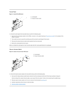
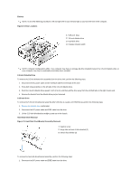
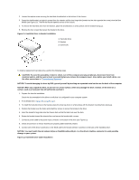
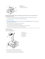
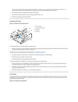
Figure 16. PCI/ISA Riser Board (Optional) 1 Auxiliary power indicator LED (AUX_LED) 2 Wakeup On LAN (WOL) connector 3 PCI expansion slot 1 (PCI1) 4 PCI expansion slot 2 (PCI2) 5 PCI expansion slot 3 (PCI3) 1 Auxiliary power LED (AUX_LED) 2 ISA expansion-card connector 1 (ISA1) 3 ISA expansion-card connector 2 (ISA2) 4 Remote Wakeup header (WOL) 5 PCI expansion-card connector 1 (PCI1) 6 PCI expansion-card connector 2 (PCI2) NOTE: The ISA expansion-card connector 1 and PCI expansion-card connector 2 share an expansion slot; only one of these two connectors can be used at any given time. To remove the riser board, perform the following steps. CAUTION: Ground yourself by touching an unpainted metal surface on the back of the computer. 1. Remove the expansion-card cage. 2. Remove the expansion cards installed in the slots. 3. Remove the screws securing the riser board to the expansion-card cage. 4. Lift the riser board off the expansion-card cage. System Board Components Figure 17 shows the system board and the location of all its sockets and connectors. Figure 17. System Board Components 1 Line-in connector
-
 1
1 -
2
-
3
-
4
-
5
-
 6
6 -
 7
7 -
 8
8 -
 9
9 -
 10
10 -
 11
11 -
 12
12 -
 13
13 -
 14
14 -
 15
15 -
 16
16 -
17
-
18
-
19
-
20
-
21
-
22
-
23
-
24
-
25
-
26
-
27
-
28
-
29
-
30
-
31
-
32
-
33
-
34
-
35
-
36
-
37
-
38
-
39
-
40
-
41
-
42
-
43
-
44
-
45
-
46
-
47
-
48
-
49
-
50
-
51
-
52
-
53
-
54
-
55
-
56
-
57
-
58
-
59
-
60
-
61
-
62
-
63
-
64
-
65
-
66
-
67
-
68
-
69
-
70
-
71
-
72
-
73
-
74
-
75
-
76
-
77
-
78
-
79
 |
 |
