Dell OptiPlex GX200 Service Manual - Page 71
Riser Board, System Board Components
 |
View all Dell OptiPlex GX200 manuals
Add to My Manuals
Save this manual to your list of manuals |
Page 71 highlights
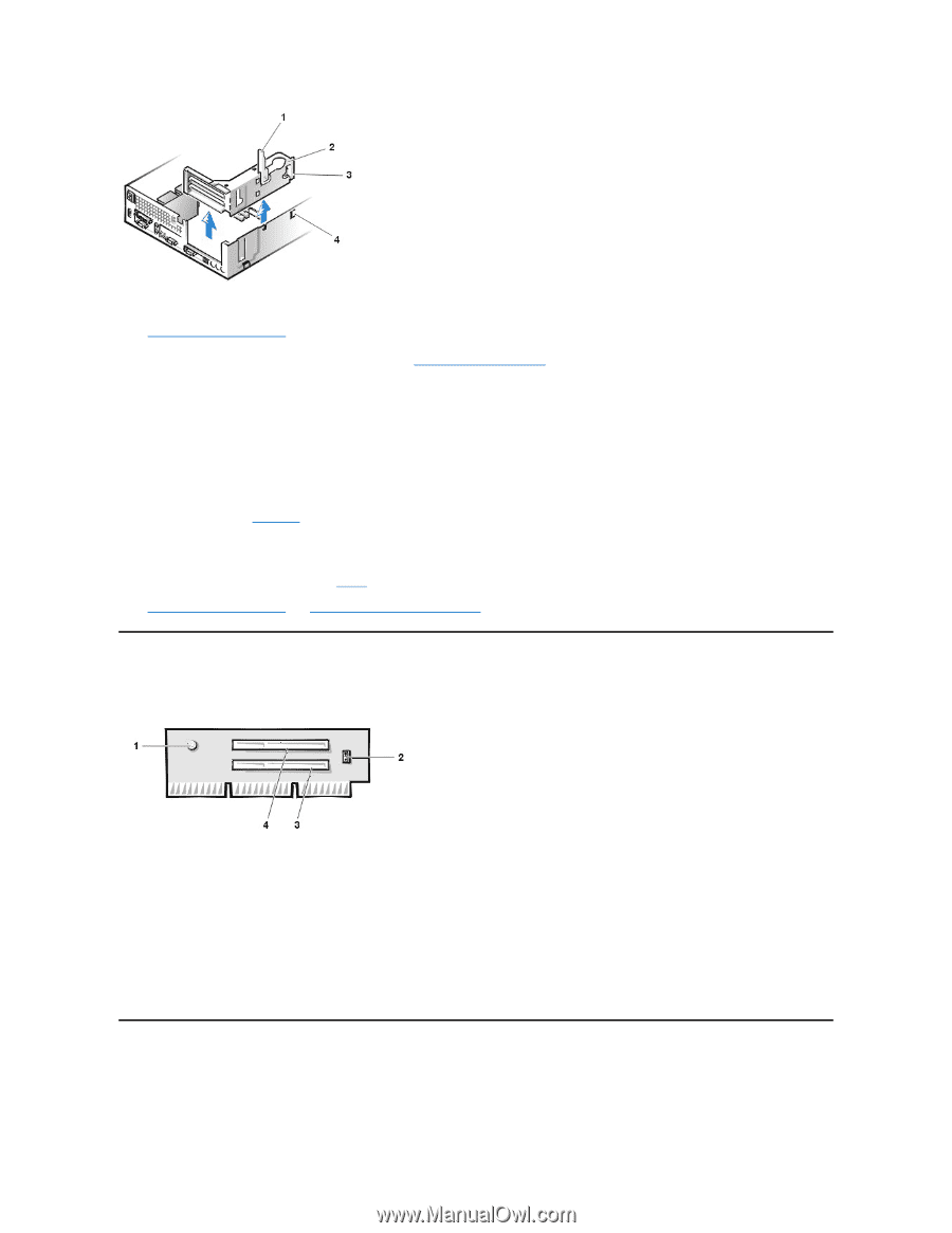
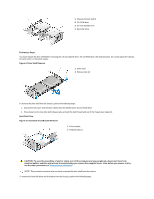
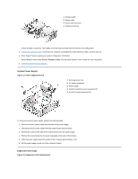
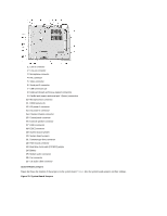
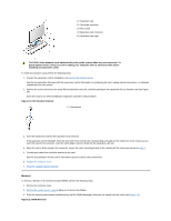
1 Securing lever 2 Expansion-card cage 3 Tabs (2) 4 Hooks (2) To remove the expansion-card cage from the chassis, perform the following steps: 1. Remove the computer cover. NOTICE: Use a wrist grounding strap as explained in "Precautionary Measures." 2. Examine the cables connected to expansion cards through the back-panel openings, and disconnect any cables that will not reach to where the cage must be placed when it is removed from the chassis. 3. Locate the securing lever and rotate the lever upward until it stops in an upright position. 4. Lift the expansion-card cage up and out of the chassis. To replace the expansion-card cage into the chassis, perform the following steps: 1. With the securing lever in the upright position, align the tabs in the side of the expansion-card cage with the mating hooks on the left side of the chassis wall (see Figure 18). Slide the expansion-card cage into place. 2. Rotate the securing lever downward until it is flush with the top side of the chassis. Make sure that the riser board is fully seated in the RISER connector on the system board. 3. Reconnect any cables you removed in step 2 of the previous procedure. 4. Replace the computer cover and reset the chassis intrusion detector. Riser Board Figure 19. PCI Riser Board 1 Auxiliary power indicator LED (AUX_LED) 2 Wakeup On LAN jumper (WOL) 3 PCI expansion slot 1 (PCI1) 4 PCI expansion slot 2 (PCI2) The chassis has a PCI riser board that has two PCI expansion-card connectors (see Figure 19). To remove the PCI riser board, perform the following steps: 1. Remove the expansion-card cage. 2. Remove the expansion cards installed in the slots. 3. Remove the screws securing the riser board to the expansion-card cage. 4. Lift the riser board off the expansion-card cage. System Board Components Figure 20 shows the system board and the location of all its sockets and connectors. Figure 20. System Board Components
-
 1
1 -
2
-
3
-
4
-
5
-
6
-
7
-
8
-
9
-
10
-
11
-
12
-
13
-
14
-
15
-
16
-
17
-
18
-
19
-
20
-
21
-
22
-
23
-
24
-
25
-
26
-
27
-
28
-
29
-
30
-
31
-
32
-
33
-
34
-
35
-
36
-
37
-
38
-
39
-
40
-
41
-
42
-
43
-
44
-
45
-
46
-
47
-
48
-
49
-
50
-
51
-
52
-
53
-
54
-
55
-
56
-
57
-
58
-
59
-
60
-
61
-
62
-
63
-
64
-
65
-
 66
66 -
 67
67 -
 68
68 -
 69
69 -
 70
70 -
 71
71 -
 72
72 -
 73
73 -
 74
74 -
 75
75 -
 76
76 -
77
-
78
-
79
 |
 |