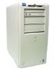
Dell OptiPlex GX200 Service Manual - Page 9
System Power Supply
 |
View all Dell OptiPlex GX200 manuals
Add to My Manuals
Save this manual to your list of manuals |
Page 9 highlights
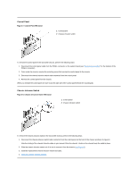
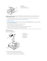
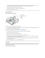
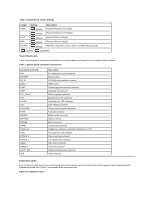
1 Power cable 2 EIDE interface cable 3 IDE1 connector on system board NOTICE: You must attach the blue connector on the EIDE interface cable to the IDE1 connector on the system board to avoid possible damage to your system. 10. If it is not already connected, connect the blue connector on the EIDE interface cable to the IDE1 connector on the system board. To locate the IDE1 connector on the system board, see "System Board Components." 11. Replace the computer cover. 12. Reset the chassis intrusion detector. While in System Setup, update the appropriate Primary Drive option, 0 or 1 (see the online System User's Guide for complete information). 13. Partition and logically format your drive before you proceed to the next step. See the documentation for your operating system for instructions. 14. If the drive you just installed is the primary drive, install your operating system on the hard-disk drive. For instructions, refer to the documentation that came with your operating system. System Power Supply Figure 13. Power Supply Removal 1 AC power cord 2 AC power receptacle 3 Power supply 4 DC power cables 5 Securing screw To remove the system power supply, perform the following steps: 1. Disconnect the AC power cable from the back of the power supply. 2. Disconnect the DC power cables from the system board and the drives.
-
 1
1 -
2
-
3
-
 4
4 -
 5
5 -
 6
6 -
 7
7 -
 8
8 -
 9
9 -
 10
10 -
 11
11 -
 12
12 -
 13
13 -
 14
14 -
15
-
16
-
17
-
18
-
19
-
20
-
21
-
22
-
23
-
24
-
25
-
26
-
27
-
28
-
29
-
30
-
31
-
32
-
33
-
34
-
35
-
36
-
37
-
38
-
39
-
40
-
41
-
42
-
43
-
44
-
45
-
46
-
47
-
48
-
49
-
50
-
51
-
52
-
53
-
54
-
55
-
56
-
57
-
58
-
59
-
60
-
61
-
62
-
63
-
64
-
65
-
66
-
67
-
68
-
69
-
70
-
71
-
72
-
73
-
74
-
75
-
76
-
77
-
78
-
79
 |
 |
