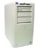
Dell OptiPlex GX200 Service Manual - Page 13
Expansion Cards - bios
 |
View all Dell OptiPlex GX200 manuals
Add to My Manuals
Save this manual to your list of manuals |
Page 13 highlights
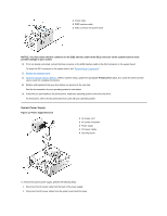
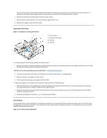
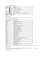
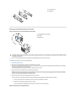
Table 1. System-Board Jumper Settings Jumper PSWD SAFE BIOS RTCRST Setting (default) (default) (default) (default) (default) Description Password features are enabled. Password features are disabled. Reserved (do not change). Reserved (do not change). Real-time clock reset. Can be used for troubleshooting purposes. jumpered unjumpered System Board Labels Table 2 lists the labels for connectors and sockets on your system board, and it gives a brief description of their functions. Table 2. System Board Connectors and Sockets Connector or Socket AMC BATTERY CD_IN RIMM_x DSKT ENET EXT_SPKR FAN HDLED IDEn INTRUDER KYBD MODEM MONITOR MOUSE PANEL PARALLEL PCIn* POWER_1 POWER_2 RISER SERIALn SLOT1_PRI USB Description ATI multimedia channel connector Battery socket CD-ROM audio interface connector RIMM socket Diskette/tape drive interface connector Integrated NIC connector External speaker connector Microprocessor fan connector Hard-disk drive LED connector EIDE interface connector Chassis intrusion switch connector Keyboard connector Modem audio connector Video connector Mouse connector Control panel connector Parallel port connector; sometimes referred to as LPT1 PCI expansion-card connector Main power input connector 3.3-V power input connector Riser board connector Serial port connector Primary microprocessor connector USB connectors Expansion Cards Each GX200 low-profile chassis can accommodate 32-bit PCI expansion cards and 16-bit and 8-bit ISA expansion cards, depending on the installed riser board. See Figure 19 for examples of the expansion cards. Figure 19. Expansion Cards
-
 1
1 -
2
-
3
-
4
-
5
-
6
-
7
-
 8
8 -
 9
9 -
 10
10 -
 11
11 -
 12
12 -
 13
13 -
 14
14 -
 15
15 -
 16
16 -
 17
17 -
 18
18 -
19
-
20
-
21
-
22
-
23
-
24
-
25
-
26
-
27
-
28
-
29
-
30
-
31
-
32
-
33
-
34
-
35
-
36
-
37
-
38
-
39
-
40
-
41
-
42
-
43
-
44
-
45
-
46
-
47
-
48
-
49
-
50
-
51
-
52
-
53
-
54
-
55
-
56
-
57
-
58
-
59
-
60
-
61
-
62
-
63
-
64
-
65
-
66
-
67
-
68
-
69
-
70
-
71
-
72
-
73
-
74
-
75
-
76
-
77
-
78
-
79
 |
 |
