Dell OptiPlex GX200 Service Manual - Page 79
Remove the RIMMs
 |
View all Dell OptiPlex GX200 manuals
Add to My Manuals
Save this manual to your list of manuals |
Page 79 highlights
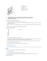
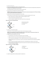
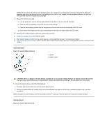
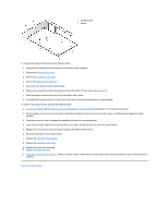
1 System board 2 Screw To remove the system board, perform the following steps: 1. Disconnect all cables from their connectors at the back of the computer. 2. Remove the drive shelf assembly. 3. Remove the expansion-card cage. 4. Remove the hard-disk drive/bracket. 5. Disconnect all cables from the system board. 6. Remove the screw that secures the system board to the bottom of the chassis (see Figure 31). 7. Slide the system board toward the front of the chassis until it stops. 8. Carefully lift the system board out of the chassis (be sure to lift evenly and not twist the system board). To install a new system board, perform the following steps: 1. Remove the RIMMs and the microprocessor/cooling fan/heat sink assembly and install them on the replacement board. 2. Set the jumpers on the new system board so that they are identical to those on the old board, unless a microprocessor upgrade is being installed. 3. Push down near each slot to engage the grounding clip onto its corresponding tab. 4. Push evenly on both sides of the system board as you slide it into position (do not twist the system board). 5. Replace the screw that secures the system board to the bottom of the chassis. 6. Reconnect all cables to the system board. 7. Replace the hard-disk drive/bracket. 8. Replace the expansion-card cage. 9. Replace the drive shelf assembly. 10. Replace the computer cover. 11. Reset the chassis intrusion detector. While in System Setup, confirm that the system data area correctly identifies the type of microprocessor installed. Back to Contents Page
-
 1
1 -
2
-
3
-
4
-
5
-
6
-
7
-
8
-
9
-
10
-
11
-
12
-
13
-
14
-
15
-
16
-
17
-
18
-
19
-
20
-
21
-
22
-
23
-
24
-
25
-
26
-
27
-
28
-
29
-
30
-
31
-
32
-
33
-
34
-
35
-
36
-
37
-
38
-
39
-
40
-
41
-
42
-
43
-
44
-
45
-
46
-
47
-
48
-
49
-
50
-
51
-
52
-
53
-
54
-
55
-
56
-
57
-
58
-
59
-
60
-
61
-
62
-
63
-
64
-
65
-
66
-
67
-
68
-
69
-
70
-
71
-
72
-
73
-
 74
74 -
 75
75 -
 76
76 -
 77
77 -
 78
78 -
 79
79
 |
 |
