Dell OptiPlex GX200 Service Manual - Page 74
Bit PCI Expansion Card Example, Expansion Card Removal, Expansion Card
 |
View all Dell OptiPlex GX200 manuals
Add to My Manuals
Save this manual to your list of manuals |
Page 74 highlights
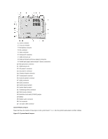
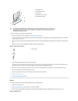
MOUSE PANEL PARALLEL PCIn* POWER_1 POWER_2 RISER SERIALn SLOT1_PRI USB Mouse connector Control panel connector Parallel port connector; sometimes referred to as LPT1 PCI expansion-card connector Main power input connector 3.3-V power input connector Riser board connector Serial port connector Primary microprocessor connector USB connectors Expansion Cards The small form-factor GX200 chassis can accommodate up to two half-length 32-bit PCI expansion cards. Figure 22 shows an example of a 32-bit PCI expansion card. Figure 22. 32-Bit PCI Expansion Card Example Expansion Card Removal To remove an expansion card, perform the following steps: 1. Remove the computer cover. 2. If necessary, disconnect any cables connected to the card. 3. Remove the expansion-card cage. 4. Remove the screw on the mounting bracket of the card you want to remove. 5. Grasp the card by its outside corners, and ease it out of its connector. 6. If you are removing the card permanently, install a metal filler bracket over the empty card-slot opening. NOTE: Installing filler brackets over empty card-slot openings is necessary to maintain Federal Communications Commission (FCC) certification of the system. The brackets also keep dust and dirt out of your computer. 7. Replace the computer cover, and reconnect your computer and peripherals to their electrical outlets and turn them on. 8. Reset the chassis intrusion detector. Figure 23. Expansion Card Installation
-
 1
1 -
2
-
3
-
4
-
5
-
6
-
7
-
8
-
9
-
10
-
11
-
12
-
13
-
14
-
15
-
16
-
17
-
18
-
19
-
20
-
21
-
22
-
23
-
24
-
25
-
26
-
27
-
28
-
29
-
30
-
31
-
32
-
33
-
34
-
35
-
36
-
37
-
38
-
39
-
40
-
41
-
42
-
43
-
44
-
45
-
46
-
47
-
48
-
49
-
50
-
51
-
52
-
53
-
54
-
55
-
56
-
57
-
58
-
59
-
60
-
61
-
62
-
63
-
64
-
65
-
66
-
67
-
68
-
 69
69 -
 70
70 -
 71
71 -
 72
72 -
 73
73 -
 74
74 -
 75
75 -
 76
76 -
 77
77 -
 78
78 -
 79
79
 |
 |