Dell PowerConnect 5316M User's Guide - Page 25
Introduction, PowerConnect 5316M and the Dell Modular Server System - user guide
 |
View all Dell PowerConnect 5316M manuals
Add to My Manuals
Save this manual to your list of manuals |
Page 25 highlights
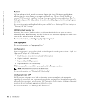
Introduction NOTICE: Before proceeding, read the release notes for this product. The release notes can be downloaded from support.dell.com. This User's Guide contains the information needed for installing, configuring and maintaining the Ethernet Switch Module. PowerConnect 5316M and the Dell Modular Server System The Dell Modular Server System is based upon the chassis that integrates up to ten Server Modules, up to four I/O modules (including the Ethernet Switch Module), and one or two system management modules called the Dell Remote Access Controller / Modular Chassis (DRAC/MC). For a list of supported options for the Dell Modular Server System, go to support.dell.com. The Ethernet Switch Module provides switching functions for the Dell Modular Server System. The DRAC/MCs provide a single point of control for the Dell Modular Server System. The PowerConnect 5316M Ethernet Switch Modules are 16-port Ethernet switch modules connected to Server Modules through the Dell Modular Server Chassis mid-plane. The ports of the Ethernet Switch Module are divided into internal and external ports. • External ports - 6 external RJ-45 connectors for 10/100/1000 Base-T copper ports (uplinks) used for connecting Server Modules to the network. • Internal ports - 10 internal ports connected to Server Modules through the Dell Modular Server Chassis mid-plane. On every Internal Port the speed is fixed to 1000 Mbps. The console connection to the Ethernet Switch Module is provided only through the DRAC/MC. No access point is provided on the Ethernet Switch Module front panel. For debugging and management purposes, a UART bus of each Ethernet Switch Module is connected to the DRAC/MC. The DRAC/MC can re-direct the serial console interface to only one switch at a time. The Ethernet Switch Module receives a power supply (12 V dc) through the mid-plane. A single system LED indicates the Ethernet Switch Module status, which is controlled by the DRAC/MC. The following figure illustrates the PowerConnect 5316M: Introduction 9
-
 1
1 -
2
-
3
-
4
-
5
-
6
-
7
-
8
-
9
-
10
-
11
-
12
-
13
-
14
-
15
-
16
-
17
-
18
-
19
-
 20
20 -
 21
21 -
 22
22 -
 23
23 -
 24
24 -
 25
25 -
 26
26 -
 27
27 -
 28
28 -
 29
29 -
 30
30 -
31
-
32
-
33
-
34
-
35
-
36
-
37
-
38
-
39
-
40
-
41
-
42
-
43
-
44
-
45
-
46
-
47
-
48
-
49
-
50
-
51
-
52
-
53
-
54
-
55
-
56
-
57
-
58
-
59
-
60
-
61
-
62
-
63
-
64
-
65
-
66
-
67
-
68
-
69
-
70
-
71
-
72
-
73
-
74
-
75
-
76
-
77
-
78
-
79
-
80
-
81
-
82
-
83
-
84
-
85
-
86
-
87
-
88
-
89
-
90
-
91
-
92
-
93
-
94
-
95
-
96
-
97
-
98
-
99
-
100
-
101
-
102
-
103
-
104
-
105
-
106
-
107
-
108
-
109
-
110
-
111
-
112
-
113
-
114
-
115
-
116
-
117
-
118
-
119
-
120
-
121
-
122
-
123
-
124
-
125
-
126
-
127
-
128
-
129
-
130
-
131
-
132
-
133
-
134
-
135
-
136
-
137
-
138
-
139
-
140
-
141
-
142
-
143
-
144
-
145
-
146
-
147
-
148
-
149
-
150
-
151
-
152
-
153
-
154
-
155
-
156
-
157
-
158
-
159
-
160
-
161
-
162
-
163
-
164
-
165
-
166
-
167
-
168
-
169
-
170
-
171
-
172
-
173
-
174
-
175
-
176
-
177
-
178
-
179
-
180
-
181
-
182
-
183
-
184
-
185
-
186
-
187
-
188
-
189
-
190
-
191
-
192
-
193
-
194
-
195
-
196
-
197
-
198
-
199
-
200
-
201
-
202
-
203
-
204
-
205
-
206
-
207
-
208
-
209
-
210
-
211
-
212
-
213
-
214
-
215
-
216
-
217
-
218
-
219
-
220
-
221
-
222
-
223
-
224
-
225
-
226
-
227
-
228
-
229
-
230
-
231
-
232
-
233
-
234
-
235
-
236
-
237
-
238
-
239
-
240
-
241
-
242
-
243
-
244
-
245
-
246
-
247
-
248
-
249
-
250
-
251
-
252
-
253
-
254
-
255
-
256
-
257
-
258
-
259
-
260
-
261
-
262
-
263
-
264
-
265
-
266
-
267
-
268
-
269
-
270
-
271
-
272
-
273
-
274
-
275
-
276
-
277
-
278
-
279
-
280
-
281
-
282
-
283
-
284
-
285
-
286
-
287
-
288
-
289
-
290
-
291
-
292
-
293
-
294
-
295
-
296
-
297
-
298
-
299
-
300
-
301
-
302
-
303
-
304
-
305
-
306
-
307
-
308
-
309
-
310
-
311
-
312
-
313
-
314
-
315
-
316
-
317
-
318
-
319
-
320
-
321
-
322
-
323
-
324
-
325
-
326
-
327
-
328
-
329
-
330
-
331
-
332
-
333
-
334
 |
 |
