Dell PowerConnect 5316M User's Guide - Page 39
Installing the Ethernet Switch Module, Installation Precautions, Overview
 |
View all Dell PowerConnect 5316M manuals
Add to My Manuals
Save this manual to your list of manuals |
Page 39 highlights
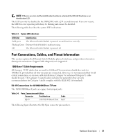
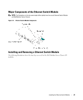
Installing the Ethernet Switch Module This section contains information about Ethernet Switch Module unpacking, installation, and cable connections. Installation Precautions CAUTION Before performing any of the following procedures, read and follow the safety instructions located in the Product Information Guide included in the Dell Documentation. CAUTION Observe the following points before performing the procedures in this section: • Observe and follow the service markings. Do not service any Ethernet Switch Module except as explained in the system documentation. Opening or removing covers marked with a triangular symbol with a lighting bolt may cause electrical shock. These components are to be serviced by trained service technicians only. • Ensure that the Ethernet Switch Module is not exposed to water. • Ensure that the Ethernet Switch Module is not exposed to radiators or heat sources. • Do not push foreign objects into the Dell Modular Server Chassis I/O Module bays, as it may cause a fire or electric shock. • Use the Ethernet Switch Module only with approved equipment. • Allow the Ethernet switch module to cool before removing covers or touching internal equipment. • Ensure that the airflow around the front, sides, and back of the Dell Modular Server Chassis is not restricted. Overview The Ethernet Switch Module is installed in one of the Chassis I/O Module bays of the Dell Modular Server Chassis. For the details on the number, types and location of the module bays, and for additional information on the entire Modular Server System, see Dell PowerEdge 1855 Systems User's Guide and Dell PowerEdge Installation and Troubleshooting Guide. The process of installing an Ethernet Switch Module into a Dell Modular Server Chassis consists of both hardware and software instructions. The process consists of three main functions: physically installing the Ethernet Switch Module into the Dell Modular Server Chassis, connecting the RS- Installing the Ethernet Switch Module 23
-
 1
1 -
2
-
3
-
4
-
5
-
6
-
7
-
8
-
9
-
10
-
11
-
12
-
13
-
14
-
15
-
16
-
17
-
18
-
19
-
20
-
21
-
22
-
23
-
24
-
25
-
26
-
27
-
28
-
29
-
30
-
31
-
32
-
33
-
 34
34 -
 35
35 -
 36
36 -
 37
37 -
 38
38 -
 39
39 -
 40
40 -
 41
41 -
 42
42 -
 43
43 -
 44
44 -
45
-
46
-
47
-
48
-
49
-
50
-
51
-
52
-
53
-
54
-
55
-
56
-
57
-
58
-
59
-
60
-
61
-
62
-
63
-
64
-
65
-
66
-
67
-
68
-
69
-
70
-
71
-
72
-
73
-
74
-
75
-
76
-
77
-
78
-
79
-
80
-
81
-
82
-
83
-
84
-
85
-
86
-
87
-
88
-
89
-
90
-
91
-
92
-
93
-
94
-
95
-
96
-
97
-
98
-
99
-
100
-
101
-
102
-
103
-
104
-
105
-
106
-
107
-
108
-
109
-
110
-
111
-
112
-
113
-
114
-
115
-
116
-
117
-
118
-
119
-
120
-
121
-
122
-
123
-
124
-
125
-
126
-
127
-
128
-
129
-
130
-
131
-
132
-
133
-
134
-
135
-
136
-
137
-
138
-
139
-
140
-
141
-
142
-
143
-
144
-
145
-
146
-
147
-
148
-
149
-
150
-
151
-
152
-
153
-
154
-
155
-
156
-
157
-
158
-
159
-
160
-
161
-
162
-
163
-
164
-
165
-
166
-
167
-
168
-
169
-
170
-
171
-
172
-
173
-
174
-
175
-
176
-
177
-
178
-
179
-
180
-
181
-
182
-
183
-
184
-
185
-
186
-
187
-
188
-
189
-
190
-
191
-
192
-
193
-
194
-
195
-
196
-
197
-
198
-
199
-
200
-
201
-
202
-
203
-
204
-
205
-
206
-
207
-
208
-
209
-
210
-
211
-
212
-
213
-
214
-
215
-
216
-
217
-
218
-
219
-
220
-
221
-
222
-
223
-
224
-
225
-
226
-
227
-
228
-
229
-
230
-
231
-
232
-
233
-
234
-
235
-
236
-
237
-
238
-
239
-
240
-
241
-
242
-
243
-
244
-
245
-
246
-
247
-
248
-
249
-
250
-
251
-
252
-
253
-
254
-
255
-
256
-
257
-
258
-
259
-
260
-
261
-
262
-
263
-
264
-
265
-
266
-
267
-
268
-
269
-
270
-
271
-
272
-
273
-
274
-
275
-
276
-
277
-
278
-
279
-
280
-
281
-
282
-
283
-
284
-
285
-
286
-
287
-
288
-
289
-
290
-
291
-
292
-
293
-
294
-
295
-
296
-
297
-
298
-
299
-
300
-
301
-
302
-
303
-
304
-
305
-
306
-
307
-
308
-
309
-
310
-
311
-
312
-
313
-
314
-
315
-
316
-
317
-
318
-
319
-
320
-
321
-
322
-
323
-
324
-
325
-
326
-
327
-
328
-
329
-
330
-
331
-
332
-
333
-
334
 |
 |
