Dell PowerConnect Brocade M6505 Brocade 7.1.0 EZSwitchSetup Administrator's Gu - Page 31
Connecting devices and completing the setup
 |
View all Dell PowerConnect Brocade M6505 manuals
Add to My Manuals
Save this manual to your list of manuals |
Page 31 highlights
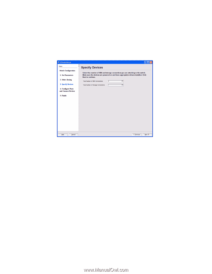
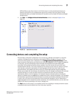
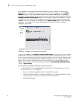
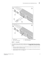
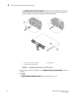
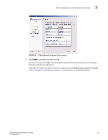
Connecting devices and completing the setup 2 EZSwitchSetup uses these values to verify that all your current and planned devices are properly connected for the zoning scheme that will be created. Note that Typical Zoning ensures that every connected host device will be able to communicate with every connected storage device. 3. Click Next. The Configure Ports and Connect Devices window is displayed (Figure 16 on page 22). FIGURE 15 Specify Devices window Connecting devices and completing the setup The final step in the switch configuration is to connect your devices to the switch in a way that matches a configured array of connection reservations (HBA or storage) on the ports. In the interactive switch graphic that is displayed on the Configure Ports and Connect Devices window, these connection reservations are shown by the letters H or S against a blue or green background on the ports, and will automatically match the types of the devices that have already been connected, with existing connections shown as green lines that connect the ports with icons representing the devices. If you have indicated on the previous screen that you intend to connect more devices, connection reservations of matching types will also have been made for your planned devices, with dotted blue lines to show you where these devices should be attached. Finally, as you attach the new devices, the dotted blue lines will change to solid green (for correctly attached devices) or to solid red (when devices are attached at ports with non-matching reservations). When a red line appears, the mismatch may be corrected either by moving the device to a different port as suggested by a dotted blue line for a device of that type, or by changing the reservation type of the port where the device is currently connected by clicking on the port icon. In either case, the solid red and dotted blue lines should both disappear, and be replaced by a single solid green line to indicate the correct connection. For connected devices, you can also view details of the device by pausing on the host or storage icon. The Next button for this screen is not enabled until all non-matching or missing connection issues (indicated by solid red and dotted blue lines) have been resolved. EZSwitchSetup Administrator's Guide 21 53-1002744-01
-
 1
1 -
2
-
3
-
4
-
5
-
6
-
7
-
8
-
9
-
10
-
11
-
12
-
13
-
14
-
15
-
16
-
17
-
18
-
19
-
20
-
21
-
22
-
23
-
24
-
25
-
 26
26 -
 27
27 -
 28
28 -
 29
29 -
 30
30 -
 31
31 -
 32
32 -
 33
33 -
 34
34 -
 35
35 -
 36
36 -
37
-
38
-
39
-
40
-
41
-
42
-
43
-
44
-
45
-
46
-
47
-
48
-
49
-
50
-
51
-
52
-
53
-
54
-
55
-
56
-
57
-
58
-
59
-
60
-
61
-
62
-
63
-
64
 |
 |