Dell PowerConnect Brocade M6505 Brocade 7.1.0 EZSwitchSetup Administrator's Gu - Page 32
Previous, Specify, Devices, Con Ports and Connect Devices, Display Devices, Custom Zoning
 |
View all Dell PowerConnect Brocade M6505 manuals
Add to My Manuals
Save this manual to your list of manuals |
Page 32 highlights
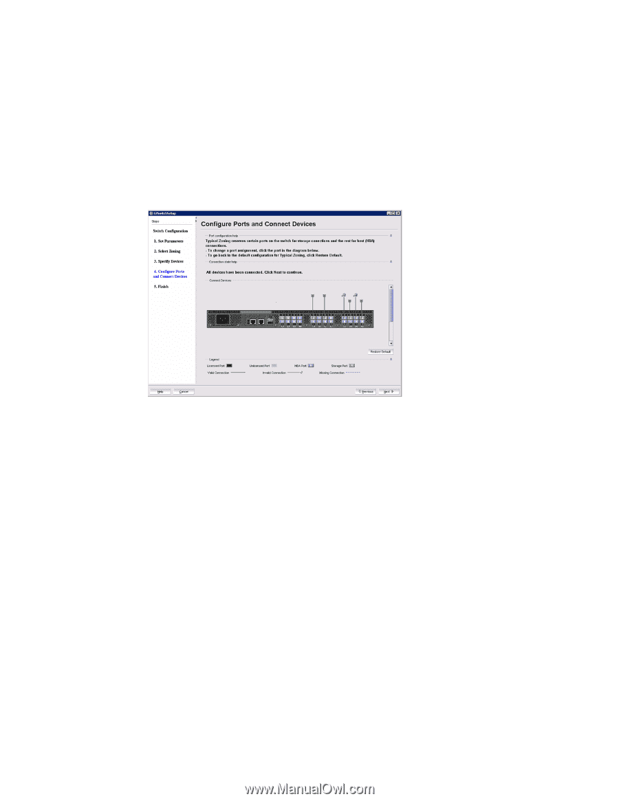
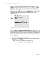
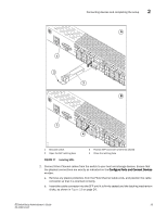
2 Connecting devices and completing the setup If you change your mind about the number of devices you want to connect, you can click the Previous button and adjust the values you have selected in the device type lists on the Specify Devices window. You must always select at least as many devices of each type as have been connected, and you must also connect as many devices of each type as you have selected. On the Configure Ports and Connect Devices window, you can also pre-reserve some additional currently unoccupied ports for future HBA or storage connections. These additional reservations are also reflected in the zoning scheme, and are shown on the Display Devices window in the EZManager application to remind you where these additional devices can be connected. The default reservation type is HBA. FIGURE 16 Configure Ports and Connect Devices window When you click Next on the Configure Ports and Connect Devices window, if Typical Zoning is used, the final set of connection reservations shown on the screen is translated internally into a zoning scheme that ensures that every correctly connected host device can communicate separately with every correctly connected storage device. If this is not what you want (for example, if you want to partition your devices so that each HBA can communicate with some storage devices but not others), then you should re-run the Setup wizard and select Custom Zoning or Advanced Zoning instead of Typical Zoning. Use the following procedure to make the physical connections. 1. Install the small form-factor pluggable (SFP) transceivers in the Fibre Channel ports shown onscreen. (See Figure 17 on page 23.) a. Remove any protector plugs from the SFP transceivers to be used. b. Position and insert each SFP transceiver as required (right side up in the top row of ports and upside down in the bottom row of ports) until it is firmly seated. c. Close the latching bale. 22 EZSwitchSetup Administrator's Guide 53-1002744-01
-
 1
1 -
2
-
3
-
4
-
5
-
6
-
7
-
8
-
9
-
10
-
11
-
12
-
13
-
14
-
15
-
16
-
17
-
18
-
19
-
20
-
21
-
22
-
23
-
24
-
25
-
26
-
 27
27 -
 28
28 -
 29
29 -
 30
30 -
 31
31 -
 32
32 -
 33
33 -
 34
34 -
 35
35 -
 36
36 -
 37
37 -
38
-
39
-
40
-
41
-
42
-
43
-
44
-
45
-
46
-
47
-
48
-
49
-
50
-
51
-
52
-
53
-
54
-
55
-
56
-
57
-
58
-
59
-
60
-
61
-
62
-
63
-
64
 |
 |