Dell PowerConnect W-6000 Installation Guide - Page 18
Status, Description
 |
View all Dell PowerConnect W-6000 manuals
Add to My Manuals
Save this manual to your list of manuals |
Page 18 highlights
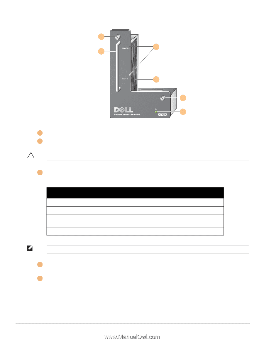
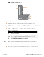
Figure 5 Dell W-6000 controller Series Fan Tray 1 4 2 5 1 3 1 Module Fastening Screws: These captive screws are used for securing the module into the chassis fan tray slot. 2 Module Handle: This handle is used for removing or inserting the module into the chassis. CAUTION: Do not use the fan tray handle to lift or move the W-6000 controller. Serious damage could result. 3 Fan Status LED: During operation, the Fan Status LED provides the following information: Table 4 Fan Tray LED Behavior Status Description Off Green Amber Red The fan tray is not operating. The fan tray is receiving power and all three fans are operating properly. One fan has failed, but the remaining two can provide proper cooling until the fan tray can be conveniently replaced. Two or more fans have failed. Replace the fan tray immediately. NOTE: In addition to the LEDs, the fan tray status and overall chassis temperature can be viewed using the CLI. 4 Slot Labels: When the fan tray is installed in the W-6000 controller, these labels name the module slots to the immediate right of the fan tray (see Figure 1 on page 7). 5 Fans (on side): Three independent fans provide redundancy for cooling the W-6000 controller cards. 18 | The Fan Tray Dell PowerConnect W-6000 Controller | Installation Guide
-
 1
1 -
2
-
3
-
4
-
5
-
6
-
7
-
8
-
9
-
10
-
11
-
12
-
 13
13 -
 14
14 -
 15
15 -
 16
16 -
 17
17 -
 18
18 -
 19
19 -
 20
20 -
 21
21 -
 22
22 -
 23
23 -
24
-
25
-
26
-
27
-
28
-
29
-
30
-
31
-
32
 |
 |