Dell PowerConnect W-6000 Installation Guide - Page 8
Power Supply Slots: The chassis has slots for up to three power supplies. The number of power
 |
View all Dell PowerConnect W-6000 manuals
Add to My Manuals
Save this manual to your list of manuals |
Page 8 highlights
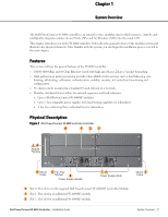
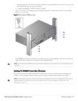
3 Slot 3: This slot for an additional W-6000M3 module. 4 Module Handles: All module handles are used only for removing and inserting the individual modules. CAUTION: Never use the module handles to lift or move the W-6000 controller chassis. Using the handles to support the chassis can result in serious damage to both the module and the chassis. 5 Holes for attaching rack mounting brackets (on side) 6 Fan Tray Module: The W-6000 controller is cooled by the air pulled through the chassis by the fan tray. The fan tray pulls air from right to left (as viewed from the front of the chassis) across the installed modules. During operation, the air vents on the left and right sides of the chassis must remain unobstructed by cables or mounting equipment. For proper air circulation, leave at least 10 cm (4 inches) of clearance on the left and right of the chassis. 7 Power Supply Slots: The chassis has slots for up to three power supplies. The number of power supplies required for your system depends on the number of W-6000M3 Controller Modules installed, and whether you wish to include redundant power supplies. See "Power Management" on page 25 for more information. Each power supply has its own power cord and power switch. CAUTION: Never insert or remove a power supply while its power switch is in the On position or while the power cord is plugged in. First verify the power switch is Off and the cord is unplugged. CAUTION: Be sure to exercise proper Electrostatic Discharge (ESD) precautions when handling the Dell W-6000 controller and its components. 8 Power Supply Handle: Use this handle for removing or inserting a power supply. 8 | System Overview Dell PowerConnect W-6000 Controller | Installation Guide
-
 1
1 -
2
-
 3
3 -
 4
4 -
 5
5 -
 6
6 -
 7
7 -
 8
8 -
 9
9 -
 10
10 -
 11
11 -
 12
12 -
 13
13 -
14
-
15
-
16
-
17
-
18
-
19
-
20
-
21
-
22
-
23
-
24
-
25
-
26
-
27
-
28
-
29
-
30
-
31
-
32
 |
 |