Dell PowerConnect W-6000 Installation Guide - Page 25
Power Management, Inserting a Power Supply
 |
View all Dell PowerConnect W-6000 manuals
Add to My Manuals
Save this manual to your list of manuals |
Page 25 highlights
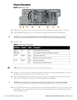
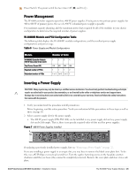
7 Power Switch: The power switch has two states: Off () and On (|). Power Management The W-6000 controller supports up to three 400 W power supplies. If using one to two primary power supplies for 400 to 800 W of primary power, the use of a 400 W redundant power supply is possible. For maximum capacity planning, add the maximum power draw required for all of the modules in your chassis configuration to determine the required number of power supplies. W-6000M3 Module and PSU Configuration Table The following table displays the W-6000M3 module configurations, and the resultant power supply configurations and power usage. Table 6 Power Supply and Module Configurations Module W-6000M3 Controller Module (130 W max power draw each) Total Power Drawn (W) Required number of PSUs Redundant number of PSUs Number of Units 1 2 3 4 130 260 390 520 1 1 1 2 1 or 2 1 or 2 1 or 2 1 Inserting a Power Supply CAUTION: Many repairs may only be done by a certified service technician. You should only perform troubleshooting and simple repairs as authorized in your product documentation, or as directed by the online or telephone service and support team. Damage due to servicing that is not authorized by Dell is not covered by your warranty. Read and follow the safety instructions that came with the product. 1. Verify you understand the procedure and all precautions. Before beginning, read the entire procedure. Verify you understand all the precautions in these steps as well as those on page 10. 2. Select a power supply slot for the power supply. The 400 W power supply (HW-PSU-400) can be installed in any power supply slot and any power supply slot can be left empty. That is, there is no specific required order of slots used for power supplies. Figure 7 400 W Power Supplies Installed If replacing a previously installed power supply, first see "Removing a Power Supply" on page 27. If you are installing a power supply in an empty slot, you may have to remove the blank cover plate first. To do this, use a #2 Phillips or cross-head screwdriver. Turn the captive fastening screws on the faceplate counterclockwise until they are loose (they cannot be completely removed). Remove the cover plate and store it in a safe place. Dell PowerConnect W-6000 Controller | Installation Guide The W-6000 Power Supply Module | 25
-
 1
1 -
2
-
3
-
4
-
5
-
6
-
7
-
8
-
9
-
10
-
11
-
12
-
13
-
14
-
15
-
16
-
17
-
18
-
19
-
 20
20 -
 21
21 -
 22
22 -
 23
23 -
 24
24 -
 25
25 -
 26
26 -
 27
27 -
 28
28 -
 29
29 -
 30
30 -
31
-
32
 |
 |
