Dell PowerConnect W-6000 Installation Guide - Page 24
Physical Description
 |
View all Dell PowerConnect W-6000 manuals
Add to My Manuals
Save this manual to your list of manuals |
Page 24 highlights
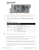
Physical Description Figure 6 400W Power Supply O.T.P DC OK AC OK 6.5A MAX 12 3 4 5 6 7 1 1 Module Fastening Screws: These two captive fastening screws hold the power supply in place in the chassis. 2 Module Handle: This handle is used for removing or inserting the module into the W-6000 chassis. CAUTION: Do not use the power supply handle to lift or move the W-6000 controller. Serious damage could result. 3 Indicator LEDs Table 5 400W Power Supply LEDs LED Name Position Status Description O.T.P. (Over Temp. Protection) DC OK Top Middle AC OK Bottom Off Red Green Red Green Red Power supply temperature is okay. Power supply fan has failed or temperature is too high. DC power output is okay. DC power output is not within tolerance. AC power input is okay. AC power input is not within tolerance. NOTE: In addition to the LEDs, the power supply status can be viewed using the CLI. 4 Air Intake Vent: This air intake vent helps the internal fan cool the power supply during operation. To prevent blockage, keep all material at least 10 cm (4 inches) from the vent. 5 Power Cord Retaining Clip: This clip fits over the power cord once the plug has been inserted into the power input socket. It helps prevent the power cord from being pulled out accidentally. CAUTION: Do not use the power cord retaining clip to remove the power supply module, or to lift or move the W-6000. 6 Power Input Socket: This power socket accepts power cords with standard IEC320 connectors. For proper safety and performance, the cord must be rated to 10 A and conform to grounded electrical standards in the country where the product is used. 24 | The W-6000 Power Supply Module Dell PowerConnect W-6000 Controller | Installation Guide
-
 1
1 -
2
-
3
-
4
-
5
-
6
-
7
-
8
-
9
-
10
-
11
-
12
-
13
-
14
-
15
-
16
-
17
-
18
-
 19
19 -
 20
20 -
 21
21 -
 22
22 -
 23
23 -
 24
24 -
 25
25 -
 26
26 -
 27
27 -
 28
28 -
 29
29 -
30
-
31
-
32
 |
 |
