Dell PowerEdge M520 Dell 10 Gb Ethernet Pass Through-k for M1000e So - Page 6
Overview
 |
View all Dell PowerEdge M520 manuals
Add to My Manuals
Save this manual to your list of manuals |
Page 6 highlights
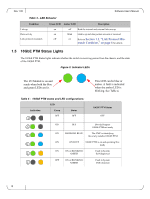
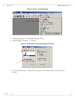
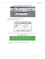
Rev 1.00 1 Overview Software User's Manual This manual explains the use of the embedded software management of the 10GbE PTM. It explains how to connect to the 10GbE PTM and to the CMC, and how to update the module and device firmware and software. This manual covers the following topics: • The rest of this section provides a high-level overview of the I/O Module structure and capabilities • Section 2, "Connecting to the 10GbE PTM CLI," on page 9, explains how to connect to the 10GbE PTM and issue CLI commands • Section 3, "Command Line Interface (CLI) Reference," on page 13 documents the CLI • Section 4, "Operating Procedures," on page 22 describes the detailed sequence of opera- tions required to achieve tasks such as software update 1.1 Port Groups The 10GbE PTM has 16 front panel ports divided into two groups: A and B. Group A consists of ports 1 through 8, providing service to blades 1 through 8, respectively; Group B consists of ports 9 through 16, providing service to blades 9 through 16, respectively. The supported link protocol for all internal ports is 10GBase KR Figure 1 shows the front panel ports and their partitioning into Group A and Group B. Figure 1: Front Panel Link Speed Port Groups DD 10 Gb Ethernet Pass Through -k 1 2 3 4 5 6 7 8 9 10 11 12 13 14 15 16 1.2 Port Link State Reflection The 10GbE PTM reflects the link state from the uplink to the downlink. When an uplink port connected to a remote peer (e.g. an Ethernet switch) is disconnected, the respective server blade will indicate link down event. When the uplink port is connected, the respective server blade will indicate link up. 1.3 Link Protocol Mismatch Condition A port may enter a link protocol mismatch condition. When in this condition, the port links (both uplink and downlink) will remain inactive. Mismatch condition is indicated by the port LEDs. Additional information about the mismatch condition is available via the CLI. Link protocol mismatch would occur under the following conditions: 6
-
 1
1 -
 2
2 -
 3
3 -
 4
4 -
 5
5 -
 6
6 -
 7
7 -
 8
8 -
 9
9 -
 10
10 -
 11
11 -
 12
12 -
13
-
14
-
15
-
16
-
17
-
18
-
19
-
20
-
21
-
22
-
23
-
24
-
25
 |
 |