Dell PowerEdge M520 Dell 10 Gb Ethernet Pass Through-k for M1000e So - Page 7
LED Behavior
 |
View all Dell PowerEdge M520 manuals
Add to My Manuals
Save this manual to your list of manuals |
Page 7 highlights
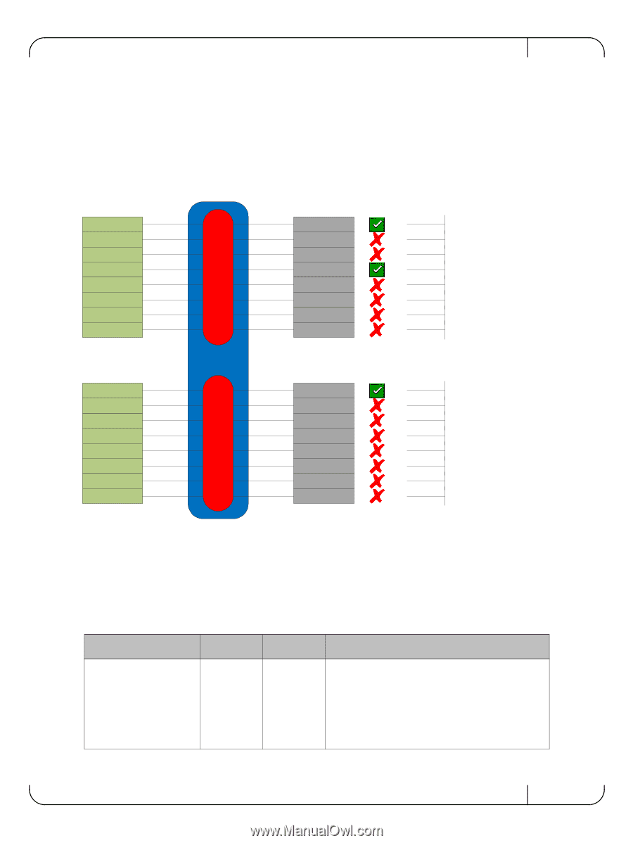
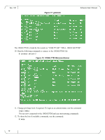
Rev 1.00 • Downlink (server blade) does not support the link protocol of the port group to which it is attached • Uplink (remote peer) does not support the link protocol of the port group to which it is attached The following drawing demonstrates link protocol mismatch conditions: Figure 2: Link Protocol Mismatch Examples Blade Configuration: Module Configuration: KR SFP+ SR Link up Port Group A KX4 SFP+ SR Blade is not KR KX SFP+ SR Blade is not KR KR SFP+ LR Link up KX4 SFP+ LR Blade is not KR KX SFP+ LR Blade is not KR KX4 No Cable No cable detected KX4 EMPTY Module not present KR KX4 KX KR KX4 KX KX4 KX4 Port Group B Passive Cable Passive Cable Passive Cable SFP SFP SFP SFP+ LRM SFP+ LR, No Link Link up Blade is not KR Blade is not KR Module is SFP (1GbE) Module is SFP (1GbE) Module is SFP (1GbE) LRM module not supported No link with remote side 1.4 LED Behavior The LED behavior is described in the following table: Table 3 - LED Behavior Condition Link down Green LED Amber LED Description off off This condition occurs in the following cases: • Server blade not present, powered down, or link is inactive • Uplink port module not present • Uplink port cable not connected • One or both of the internal and/or external links is down 7
-
 1
1 -
 2
2 -
 3
3 -
 4
4 -
 5
5 -
 6
6 -
 7
7 -
 8
8 -
 9
9 -
 10
10 -
 11
11 -
 12
12 -
13
-
14
-
15
-
16
-
17
-
18
-
19
-
20
-
21
-
22
-
23
-
24
-
25
 |
 |