Dell PowerEdge M600 Web Tools Administrator’s Guide
Dell PowerEdge M600 Manual
 |
View all Dell PowerEdge M600 manuals
Add to My Manuals
Save this manual to your list of manuals |
Dell PowerEdge M600 manual content summary:
- Dell PowerEdge M600 | Web Tools Administrator’s Guide - Page 1
DRAFT: BROCADE CONFIDENTIAL 53-1001772-01 ® 30 March 2010 Web Tools Administrator's Guide Supporting Fabric OS v6.4.0 - Dell PowerEdge M600 | Web Tools Administrator’s Guide - Page 2
any warranty, expressed or implied, concerning any equipment, equipment feature, or service offered or to be offered by Brocade. Brocade reserves the right to programming source code, please visit http://www.brocade.com/support/oscd. Brocade Communications Systems, Incorporated Corporate and Latin - Dell PowerEdge M600 | Web Tools Administrator’s Guide - Page 3
to clarify April 2006 how to configure tunnels. Updates for Fabric OS v5.2.0 and the FC4-16IP blade. Also new security for Web Tools, including Role-Based Access Control and administrative domains. September 2006 Updates to reflect interface enhancements, support for new switch types, IPv6 - Dell PowerEdge M600 | Web Tools Administrator’s Guide - Page 4
18 Encryption Blade. August 2008 Updates to add support for Virtual Fabrics, IPsec, and consistency with DCFM. November 2008 Updates to add support for Brocade 7800 Extension Switch, Brocade 8000, FCOE10-24 DCX Blade, and FX8-24 DCX Extension Blade. July 2009 Updates to add support for Brocade - Dell PowerEdge M600 | Web Tools Administrator’s Guide - Page 5
In this chapter xxi How this document is organized xxi Supported hardware and software xxii What's new in this document xxiii 7 Installing the Java plug-in on Windows 7 Java plug-in configuration 8 Configuring the Java plug-in for Windows 8 Configuring the Java plug-in for Mozilla family - Dell PowerEdge M600 | Web Tools Administrator’s Guide - Page 6
SSH client window 31 Collecting logs for troubleshooting 32 Managing Fabrics and Switches In this chapter 33 Fabric and switch management overview 33 Opening the Switch Administration window 35 Configuring IP and subnet mask information 36 Configuring Auto Refresh 36 Configuring a syslog IP - Dell PowerEdge M600 | Web Tools Administrator’s Guide - Page 7
using chassis beaconing 58 Virtual Fabrics overview 58 Selecting a logical switch from the Switch View 58 Viewing logical ports 59 Maintaining Configurations and Firmware In this chapter 61 Creating a configuration backup file 61 Restoring a configuration 63 Web Tools Administrator's Guide - Dell PowerEdge M600 | Web Tools Administrator’s Guide - Page 8
from USB storage 65 Performing a firmware download 65 SAS and SA firmware download 67 Switch configurations for mixed fabrics 67 Enabling interoperability 68 Managing Administrative Domains In this chapter 69 Administrative Domain overview 69 Requirements for Admin Domains 69 User-defined - Dell PowerEdge M600 | Web Tools Administrator’s Guide - Page 9
considerations 104 Predefined performance graphs 105 User-defined graphs 107 Canvas configurations 108 Opening the Performance Monitoring window 108 Creating basic performance monitor graphs canvas 114 Adding graphs to an existing canvas 116 Web Tools Administrator's Guide ix 53-1001772-01 - Dell PowerEdge M600 | Web Tools Administrator’s Guide - Page 10
configurations 121 Opening the Zone Administration window window configuration members 132 Renaming zone configurations 133 Cloning zone configurations 133 Deleting zone configurations 133 Enabling zone configurations 134 Disabling zone configurations 134 Displaying enabled zone configurations - Dell PowerEdge M600 | Web Tools Administrator’s Guide - Page 11
146 Port icon colors 146 LED representations 147 Brocade 48000 Director LEDs 148 Using the FC-FC Routing Service In this chapter 149 Fibre Channel Routing overview 149 Supported switches for Fibre Channel Routing 150 Setting up FC-FC routing 150 FC-FC routing management 150 Opening - Dell PowerEdge M600 | Web Tools Administrator’s Guide - Page 12
mail server on a switch 178 Configuring the e-mail alert 179 Administering Extended Fabrics In this chapter 181 Extended link buffer allocation overview 181 Configuring a port for long distance 183 Administering the iSCSI Target Gateway In this chapter 185 xii Web Tools Administrator's Guide - Dell PowerEdge M600 | Web Tools Administrator’s Guide - Page 13
and troubleshooting accessibility 199 Routing Traffic In this chapter 201 Routing overview 201 Viewing fabric shortest path first routing 202 Configuring dynamic load sharing 203 Lossless dynamic load sharing 203 Specifying frame order delivery 204 Web Tools Administrator's Guide xiii - Dell PowerEdge M600 | Web Tools Administrator’s Guide - Page 14
223 Changing the access control configuration 224 RADIUS management 224 Enabling and disabling RADIUS 225 Configuring RADIUS 225 Modifying the RADIUS server 226 Modifying the RADIUS server order 226 Removing a RADIUS server 227 Active Directory service management 227 Enabling Active - Dell PowerEdge M600 | Web Tools Administrator’s Guide - Page 15
or disabling FICON Management Server mode 244 FMS parameter configuration 245 Configuring FMS mode parameters 246 Displaying code page information 246 Viewing the control device state 247 CUP port connectivity configuration 248 Viewing CUP port connectivity configurations 248 Modifying CUP - Dell PowerEdge M600 | Web Tools Administrator’s Guide - Page 16
information that is unique to FCoE 256 Switch administration and FC0E 257 FC0E configuration tasks 257 Quality of Service configuration 258 Adding a CEE map 258 Adding a traffic class map 259 LLDP-DCBX configuration 259 Configuring global LLDP characteristics 259 Adding an LLDP profile 261 - Dell PowerEdge M600 | Web Tools Administrator’s Guide - Page 17
window, Switch tab 34 Blade tab 39 License tab 47 High Availability window, Service tab 51 High Availability window, CP tab 52 Logical switch selector 59 USB configuration upload 61 Information dialog box 62 Fabric ID selector 62 USB configuration download 63 USB Guide xvii 53-1001772-01 - Dell PowerEdge M600 | Web Tools Administrator’s Guide - Page 18
disabled 161 Port Group Configuration-view only 162 Access Gateway Auto Rebalancing 168 Fabric Watch window 172 Extended Fabric tab 182 Routing tab 202 User tab 209 Add User Account dialog box (VF 210 Add User Account dialog box (AD 210 Choices in the Secondary AAA Service drop-down menu - Dell PowerEdge M600 | Web Tools Administrator’s Guide - Page 19
Brocade switches 106 Zoning features supported in DCFM Professional and Enterprise Edition . . . . 119 QoS zone name prefixes 120 Alarm notification table fields 178 Long-distance settings and license requirements 183 iSCSI target gateway services terminology 186 User role and permissions 208 - Dell PowerEdge M600 | Web Tools Administrator’s Guide - Page 20
DRAFT: BROCADE CONFIDENTIAL xx Web Tools Administrator's Guide 53-1001772-01 - Dell PowerEdge M600 | Web Tools Administrator’s Guide - Page 21
document is organized xxi •Supported hardware and software xxii including system requirements and installation instructions. • Chapter 2, "Using Configurations and Firmware" provides information about uploading and downloading configuration files and downloading firmware Guide xxi 53-1001772-01 - Dell PowerEdge M600 | Web Tools Administrator’s Guide - Page 22
documented here apply to some switches but not to others, this guide identifies exactly which switches are supported and which are not. Although many different software and hardware configurations are tested and supported by Brocade Communications Systems, Inc. for Fabric OS v6.4.0, documenting all - Dell PowerEdge M600 | Web Tools Administrator’s Guide - Page 23
: • Port beaconing • Enhanced TI zones • WWN-based Persistent PID • WWN-N Port mapping • Switch Status Policy • Lossless DLS support • GigE ports-Media type configuration • FICON-CUP Logical Path and Link Incident Registered Recipient support Web Tools Administrator's Guide xxiii 53-1001772-01 - Dell PowerEdge M600 | Web Tools Administrator’s Guide - Page 24
bold text Identifies command names Identifies the names of user-manipulated GUI elements Identifies keywords and operands Identifies guide are presented in mixed lettercase: for example, switchShow. In actual examples, command lettercase is often all lowercase. Otherwise, this manual specifically - Dell PowerEdge M600 | Web Tools Administrator’s Guide - Page 25
. Mozilla Referenced Trademarks and Products Windows, Windows NT, Internet Explorer Oracle, Solaris Netscape Red Hat, Red Hat Network, Maximum RPM, Linux Undercover Firefox Additional information This section lists additional Brocade and industry-specific documentation that you might find helpful - Dell PowerEdge M600 | Web Tools Administrator’s Guide - Page 26
help Contact your switch support supplier for hardware, firmware, and software support, including product repairs and problem, including the switch or fabric behavior immediately following the problem, and specific questions • Description of any troubleshooting Administrator's Guide 53-1001772-01 - Dell PowerEdge M600 | Web Tools Administrator’s Guide - Page 27
chassis • Brocade 48000-Inside the chassis next to the power supply bays • Brocade DCX-On the bottom right on the port side of the chassis numbers on the WWN cards by removing the Brocade logo plate at the top of the nonport side of the chassis. Document feedback Quality Guide xxvii 53-1001772-01 - Dell PowerEdge M600 | Web Tools Administrator’s Guide - Page 28
DRAFT: BROCADE CONFIDENTIAL xxviii Web Tools Administrator's Guide 53-1001772-01 - Dell PowerEdge M600 | Web Tools Administrator’s Guide - Page 29
configuration 8 •Value line licenses 9 •Opening Web Tools 9 •Role-Based Access Control 14 •Session management 14 •Web Tools system logs 15 •Requirements for IPv6 support 16 Web Tools overview Brocade Web Tools is an embedded graphical user . Web Tools Administrator's Guide 1 53-1001772-01 - Dell PowerEdge M600 | Web Tools Administrator’s Guide - Page 30
Directory support yes yes AD Context Switching no yes AD filtered views yes yes Admin Domain Management no yes AG Management yes yes Analyze zone config no no Basic Zoning and TI Zoning yes yes Blade Management yes yes Cloning a zone no yes Configuration upload/download - Dell PowerEdge M600 | Web Tools Administrator’s Guide - Page 31
Routing and DLS Configuration no yes Security Policies Tab (like ACL) yes yes Switch Info tab yes yes Switch Status yes yes Switch View right-click options yes yes Trace dump yes yes USB Management yes yes User Management yes yes Verify and troubleshoot accessibility yes yes - Dell PowerEdge M600 | Web Tools Administrator’s Guide - Page 32
supported in Web Tools 6.1.1, but New, Edit Config, and delete are only available in DCFM. In Web Tools, non-local switch port id/WWN can be added using text box. Zone database Zone Admin summary print Configure and Java Plug-in 1.6.0_16 or later. 4 Web Tools Administrator's Guide 53-1001772-01 - Dell PowerEdge M600 | Web Tools Administrator’s Guide - Page 33
Windows 7 Windows Server 2008 Standard Windows Vista Business Windows XP, SP3 RedHat Enterprise Server 5 Advanced Platform SUSE Linux Enterprise Server Firefox 2.0 For Windows systems, a minimum a fully populated FC8-64 blade requires a minimum of 512 of Web Tools. User the following procedure to - Dell PowerEdge M600 | Web Tools Administrator’s Guide - Page 34
on page 6. FIGURE 1 Configuring Internet Explorer Deleting temporary internet these files. 1. From the Control Panel, open Java. 2. Select Click OK. 6. On the Java Control Panel, click View to review the files that are in the downloads the proper Java Plug-in. • Firefox downloads the most - Dell PowerEdge M600 | Web Tools Administrator’s Guide - Page 35
/j2se/5.0_06/index.html NOTE This URL points to a non-Brocade website and is subject to change without notice. 2. Download JRE 5.0 Update 13. 3. Follow the instructions to install the JRE. 4. Create a symbolic link from this location: $FIREFOX/plugins/libjavaplugin_oji.so To this location: $JRE - Dell PowerEdge M600 | Web Tools Administrator’s Guide - Page 36
of a switch running Fabric OS 5.2.0 or later to install JRE 1.6.0. For Fabric OS 6.3.0 install JRE 1.6.0 update 13. Web Tools guides you through the steps to download the proper Java Plug-in. Java plug-in configuration If you are managing fabrics with more than 10 switches or 1000 ports, or if you - Dell PowerEdge M600 | Web Tools Administrator’s Guide - Page 37
apply your settings and close the Java Control Panel. Value line licenses If you open exceeds the supported switch configuration limit and tells that have lower or higher firmware versions. It is important to supports both HTTP and HTTPS protocol. Web Tools Administrator's Guide 9 53-1001772-01 - Dell PowerEdge M600 | Web Tools Administrator’s Guide - Page 38
box displays. If you are using Internet Explorer, the browser window automatically closes when the login dialog box displays. NOTE If you initial setup procedure for smaller switches. Refer to EZSwitchSetup Administrator's Guide for information about the EZSwitchSetup interface. If you want to - Dell PowerEdge M600 | Web Tools Administrator’s Guide - Page 39
login window, Web Tools displays a security banner (if one is configured user name and password. If your current password has expired, you must also provide a new password and confirm the new password. Logging in to a Virtual Fabric If you are logging in to a platform that is capable of supporting - Dell PowerEdge M600 | Web Tools Administrator’s Guide - Page 40
between Home Logical Fabric and User Specified Virtual Fabric (Figure 4). other than the home logical fabric, select User Specified Logical Fabric, enter the fabric ID a platform that is capable of supporting Admin Domains, the login dialog box User Specified Domain. 2. Log in to an Admin Domain - Dell PowerEdge M600 | Web Tools Administrator’s Guide - Page 41
than the home domain, select User Specified Domain, enter the Admin Domain name or number with Admin Domain options If the user name or password is incorrect, by closing the Switch Explorer window. You might be logged out initiate a firmware download from Web Tool's Switch Administration window. In - Dell PowerEdge M600 | Web Tools Administrator’s Guide - Page 42
Control Role-Based Access Control (RBAC) defines the capabilities that a user user You have full access to all of the Web Tools features. You can perform any actions on the switch that do not affect the stored configuration close the Switch Explorer window • The session ends due Guide 53-1001772-01 - Dell PowerEdge M600 | Web Tools Administrator’s Guide - Page 43
window to close it. • Close all open Web Tools windows. NOTE If you click Logout in the Switch Explorer window, and Web Tools leaves the Temperature, Fan, Power, and the Switch status windows open, you must manually under the user home directory. • The Web Tools Switch Support Save directory - Dell PowerEdge M600 | Web Tools Administrator’s Guide - Page 44
any configured IP address. • Use a switch with v5.3.0 or later firmware to manage a mixed fabric of IPv4 and IPv6 switches. • Switches running on version 5.2.0 do not discover IPv6 address-only switches in the same fabric until the IPv4 address is configured. 16 Web Tools Administrator's Guide 53 - Dell PowerEdge M600 | Web Tools Administrator’s Guide - Page 45
window 31 •Collecting logs for troubleshooting configuration and zoning database management" on page 131. - Reporting tasks, such as viewing the status of a switch. - Monitoring tasks, such as performance monitoring, and viewing the temperature or power status. Web Tools Administrator's Guide - Dell PowerEdge M600 | Web Tools Administrator’s Guide - Page 46
View provides access to switch information: status, temperature, power, and fan data, beaconing, and the legend for the Switch View. Although clicking a button can open a separate dialog box or window displays the management tasks, all access control is established when you first log in to the - Dell PowerEdge M600 | Web Tools Administrator’s Guide - Page 47
ID, or Changing the Admin Domain 5 Switch Events and Switch Information 6 Indicator bar 7 Professional Management Tool offering 8 Switch View FIGURE 7 Switch Explorer Web Tools Administrator's Guide 19 53-1001772-01 - Dell PowerEdge M600 | Web Tools Administrator’s Guide - Page 48
config Zone folder Status button - Healthy Status button - Marginal Status button - Critical Status button - Unmonitored Switch event - Fatal Switch event - Informational 20 Web Tools Administrator's Guide 53-1001772-01 - Dell PowerEdge M600 | Web Tools Administrator’s Guide - Page 49
headers, and are replaced by right-click operations, as shown in Figure 8. Old New FIGURE 8 Right-click for Copy, Export, and Search Web Tools Administrator's Guide 21 53-1001772-01 - Dell PowerEdge M600 | Web Tools Administrator’s Guide - Page 50
Switch Admin, and Name Server dialog boxes on all mode • Last selected tab by the user • Table column sorting • Table column or Advance modes The Name Server GUI preferences that persist are only from the primary fabric configuration server (FCS) switch. Refer to Server information-This feature is available - Dell PowerEdge M600 | Web Tools Administrator’s Guide - Page 51
to display the IP address and current status. To manually refresh the status of a switch within the fabric, switches in the fabric, you can manage switches that support 6.1 and later versions (does not requires Web Tools specific Admin Domain. Web Tools Administrator's Guide 23 53-1001772-01 - Dell PowerEdge M600 | Web Tools Administrator’s Guide - Page 52
from the Admin Domain menu. 2. Click OK in the confirmation window. Switch Explorer refreshes to display the new Admin Domain context. You windows. You can choose to change the Admin Domain, which closes all the open windows, or cancel the action and return to Switch Explorer. NOTE The Telnet window - Dell PowerEdge M600 | Web Tools Administrator’s Guide - Page 53
Click the button to view temperature monitors. • Power-Click the button to view power supply information. • Fan-Click the button to the upgrade license installed: • For 7500E, FC ports 2-15 are disabled • For 7800, 4 FC ports and 2 GbE ports are enabled NOTE Blades are Guide 25 53-1001772-01 - Dell PowerEdge M600 | Web Tools Administrator’s Guide - Page 54
window by clicking these ports. For the Brocade DCX, the Port Admin view is launched for ICL ports. USB port representation For switches with USB ports, the USB Storage Management view is launched for USB ports (Figure 12). FIGURE 12 USB port storage management 26 Web Tools Administrator's Guide - Dell PowerEdge M600 | Web Tools Administrator’s Guide - Page 55
DRAFT: BROCADE CONFIDENTIAL Viewing Switch Explorer 2 NOTE Click the USB port on the switch to launch the USB Storage Management window. Switch Events and Switch Information Switch Events and Switch Information display as tab forms under Switch View. The information in the Switch Information - Dell PowerEdge M600 | Web Tools Administrator’s Guide - Page 56
where the switch was manufactured. • Name Server - Capability - Device Type - Unit Type download firmware, manage security settings, and deploy configurations display the port tool tips. Firmware versions and IP addressing are displayed for CP blades. When you rest the cursor Guide 53-1001772-01 - Dell PowerEdge M600 | Web Tools Administrator’s Guide - Page 57
or copy the information from the Port Details window. • The Configure option provides another menu of options to allow you to rename, enable, and disable ports, and to set persistent enable or disable without opening the Port Administration window. Web Tools Administrator's Guide 29 53-1001772-01 - Dell PowerEdge M600 | Web Tools Administrator’s Guide - Page 58
period." To ensure the correct information, the time field is updated along with the port statistics data after every refresh. The Name Server Zoning Database Fabric Watch Performance Monitor (This feature requires the EGM license.) Port Management FC Routing User-defined; 's Guide 53-1001772-01 - Dell PowerEdge M600 | Web Tools Administrator’s Guide - Page 59
connects to the IP interface of the switch. You cannot connect to a CP blade on a director switch through a Telnet or SSH client window opened from Web Tools, even when the blade has an IP address and supports Telnet sessions. Refer to the Fabric OS Command Reference for information about the Telnet - Dell PowerEdge M600 | Web Tools Administrator’s Guide - Page 60
exit at the prompt and press the Enter key. Collecting logs for troubleshooting If you encounter problems using the Web Tools interface, collect Java logs for use in troubleshooting. From Microsoft Windows, perform this procedure. 1. Open Control Panel and select Java. 2. Click on the Advanced tab - Dell PowerEdge M600 | Web Tools Administrator’s Guide - Page 61
IP address 37 •Configuring IP Filtering 38 •Blade management 38 •Switch configuration 40 •Switch restart 42 •System configuration parameters 42 •Licensed feature management 47 •High Availability overview 49 •Event monitoring 53 •Displaying the Name Server entries 56 •Physically locating - Dell PowerEdge M600 | Web Tools Administrator’s Guide - Page 62
Administration window is not updated automatically by Web Tools. To update the information displayed in the Switch Administration window, Switch Administration window to the switch, click Apply before closing the module or before switching to another tab. The License tab, Firmware Download tab, and - Dell PowerEdge M600 | Web Tools Administrator’s Guide - Page 63
DRAFT: BROCADE CONFIDENTIAL Fabric and switch management overview 3 Opening the Switch Administration window Most of the management procedures in this chapter are performed from the Switch Administration window. Web Tools Administrator's Guide 35 53-1001772-01 - Dell PowerEdge M600 | Web Tools Administrator’s Guide - Page 64
the switch. Close all current windows and restart Web Tools with the new IP address. NOTE The IPFC address is specific for each logical switch. The IPFC address is set to FC0 for switches that do not support Virtual Fabrics. Use the following procedure to configure the IP and subnet mask information - Dell PowerEdge M600 | Web Tools Administrator’s Guide - Page 65
to the syslog on the specified servers. Up to six servers are supported. Refer to Fabric OS Administrator's Guide for more information on configuring the syslog daemon. Use the following procedure to configure a syslog IP address. 1. Open the Switch Administration window as described in "Opening the - Dell PowerEdge M600 | Web Tools Administrator’s Guide - Page 66
IP Filtering DRAFT: BROCADE CONFIDENTIAL Configuring IP Filtering Web Tools provides the ability to control what client IP addresses may connect to a switch or fabric. Use the following procedure to set up IP Filtering. 1. Open the Switch Administration window as described in "Opening the - Dell PowerEdge M600 | Web Tools Administrator’s Guide - Page 67
in "Opening the Switch Administration window" on page 35. 2. Select the Blade tab. 3. Click Set IP address. 4. Select a slot number from the list. 5. Enter the IP address, subnet mask, and Gateway IP address. 6. Select a type from the list. Web Tools Administrator's Guide 39 53-1001772-01 - Dell PowerEdge M600 | Web Tools Administrator’s Guide - Page 68
" on page 35. 2. Select the Blade tab. 3. Click Show IP Address. 4. Scroll through the list to view all the information. 5. When you are finished, click Close. Switch configuration Use the Switch tab of the Switch Administration window to perform basic switch configuration. Figure 14 on page 34 - Dell PowerEdge M600 | Web Tools Administrator’s Guide - Page 69
service by the chassis name. If you assign meaningful chassis names and switch names, system logs are easier to use. 1. Open the Switch Administration window as described in "Opening the Switch Administration window Switch configuration parameters • A list of ISLs and ports • Name Server information - Dell PowerEdge M600 | Web Tools Administrator’s Guide - Page 70
execute the normal power-on booting sequence. 1. Open the Switch Administration window as described in "Opening the Switch Administration window" on page 35. 2. Click Reboot. 3. On the Reboot Confirmation window, click Yes to continue. 4. Click Apply. System configuration parameters You must disable - Dell PowerEdge M600 | Web Tools Administrator’s Guide - Page 71
2 Default-8 bit dynamic Default-8bit dynamic FMS is not supported Can be set Not supported Configurable Configurable Configuring fabric settings Perform the following steps to configure the fabric settings. 1. Open the Switch Administration window as described in "Opening the Switch Administration - Dell PowerEdge M600 | Web Tools Administrator’s Guide - Page 72
, devices that do not register with the Name Server are not present in the Name Server database. Per-Frame Routing Priority Select whether to select reboots, power cycles, and failovers. This mode is required fabric wide to transmit FICON data. WWN-based Persistent Set this mode to configure a PID - Dell PowerEdge M600 | Web Tools Administrator’s Guide - Page 73
DRAFT: BROCADE CONFIDENTIAL System configuration parameters 3 Configuring virtual channel settings You can configure parameters for eight virtual channels (VC) to enable fine-tuning for a specific application. You cannot modify the first two virtual channels because these are reserved for switch - Dell PowerEdge M600 | Web Tools Administrator’s Guide - Page 74
the Firmware Download tab in the Switch Administration window. Perform the following procedure to configure the signed firmware. 1. Open the Switch Administration window as described in "Opening the Switch Administration window" on page 35. 2. Select the Configure tab. 3. Select the Firmware subtab - Dell PowerEdge M600 | Web Tools Administrator’s Guide - Page 75
Firmware Download check box. 5. Click Apply. Licensed feature management The licensed features currently installed on the switch are listed in the License tab of the Switch Administration window or refer to the Fabric OS Administrator's Guide for instructions on how to obtain a license key at - Dell PowerEdge M600 | Web Tools Administrator’s Guide - Page 76
window" on page 35. 2. Select the License tab and click Add. The Add License dialog box displays. 3. Paste or enter a license key in the field. 4. Click Add License. 5. Click Refresh to display the new licenses in the License tab. Some licenses, such as the Trunking or the 7500E and 7800 upgrade - Dell PowerEdge M600 | Web Tools Administrator’s Guide - Page 77
47). The following features are supported for universal time-based license: Networking • Server Application Guide for additional information about High Availability. The High Availability window, as shown in Figure 18, displays information about the status of the HA feature on each control - Dell PowerEdge M600 | Web Tools Administrator’s Guide - Page 78
3 High Availability overview DRAFT: BROCADE CONFIDENTIAL 2. Click the HA button in the Switch View. 50 Web Tools Administrator's Guide 53-1001772-01 - Dell PowerEdge M600 | Web Tools Administrator’s Guide - Page 79
DRAFT: BROCADE CONFIDENTIAL High Availability overview 3 The High Availability dialog box displays. FIGURE 17 High Availability window, Service tab Web Tools Administrator's Guide 51 53-1001772-01 - Dell PowerEdge M600 | Web Tools Administrator’s Guide - Page 80
window contains the following two tabs: • The Service tab displays information about the switch. When the hardware is configured as a dual switch, the Service tab displays information about both switches. • The CP tab displays information about slots. For Brocade 48000 and Brocade DCX-4S, CP blades - Dell PowerEdge M600 | Web Tools Administrator’s Guide - Page 81
synchronization of services, so that a nondisruptive failover is ready. 5. Click Refresh to update the HA Status the Web Tools Switch Explorer window and all associated windows, and re-open Web chassis • The number of successive events of the same kind Web Tools Administrator's Guide 53 53 - Dell PowerEdge M600 | Web Tools Administrator’s Guide - Page 82
problems that will eventually cause a partial or complete failure of a subsystem if not corrected immediately. For example, a power and updated every 15 seconds; there is no refresh-on-demand option for switch events. For two-switch configurations, all chassis-related events 's Guide 53-1001772-01 - Dell PowerEdge M600 | Web Tools Administrator’s Guide - Page 83
fabric and switch events by time, severity, message ID, and service. You can apply either one type of filter at a time and date. 4. Click OK. The filter is enabled and the window is refreshed to show the filtered information. Filtering events by event Administrator's Guide 55 53-1001772-01 - Dell PowerEdge M600 | Web Tools Administrator’s Guide - Page 84
. The event service menu is enabled. 4. Select either Switch or Chassis from the menu to show only those messages from the logical switch or from the chassis. 5. Click OK. The filter is enabled and the window is refreshed to show the filtered information. Displaying the Name Server entries Web Tools - Dell PowerEdge M600 | Web Tools Administrator’s Guide - Page 85
Monitor > Name Server. The Name Server window displays. 2. Server. The Name Server window displays. 2. Select a device from the Domain column. 3. Click Detail View. The Name Server Information dialog box displays the information specific chassis. It is not mirrored in the Switch - Dell PowerEdge M600 | Web Tools Administrator’s Guide - Page 86
the DCFM User Manual if you are using DCFM, or Fabric OS Administrator's Guide if you are using the Fabric OS command line interface. You can use Web Tools to view Virtual Fabrics and logical switch configurations. Selecting a logical switch from the Switch View You can log in to a specific logical - Dell PowerEdge M600 | Web Tools Administrator’s Guide - Page 87
chassis interconnection. Each chassis specific configure window displays. Logical ports are displayed in the FC Ports Explorer tree structure. 2. To view logical port properties, expand the Logical Ports folder, and select a port. The General properties are displayed. Web Tools Administrator's Guide - Dell PowerEdge M600 | Web Tools Administrator’s Guide - Page 88
3 Virtual Fabrics overview DRAFT: BROCADE CONFIDENTIAL 60 Web Tools Administrator's Guide 53-1001772-01 - Dell PowerEdge M600 | Web Tools Administrator’s Guide - Page 89
this chapter •Creating a configuration backup file 61 •Restoring a configuration 63 •Admin Domain configuration maintenance 64 •Uploading and downloading from USB storage 65 •Performing a firmware download 65 •Switch configurations for mixed fabrics 67 Creating a configuration backup file Keep - Dell PowerEdge M600 | Web Tools Administrator’s Guide - Page 90
of 128 for the physical switch, chassis level configuration, and all chassis and switches. FIGURE 22 Fabric ID selector NOTE If you are using a USB device, it must be connected and mounted before you upload or download. Refer to "Uploading and downloading from USB storage" on page 65 for more - Dell PowerEdge M600 | Web Tools Administrator’s Guide - Page 91
" in the User Name field. To restore a configuration, perform the following task. 1. Open the Switch Administration window. 2. Select Show Advanced Mode. 3. Select the Configure tab. The Configure screen displays. 4. Select the Upload/Download tab. The Upload/Download configuration screen displays - Dell PowerEdge M600 | Web Tools Administrator’s Guide - Page 92
physical switch, chassis level configuration, and all chassis and switches. 9. Enter the fabric ID of the logical switch in Template Fabric ID. NOTE If you are using a USB device, it must be connected and mounted before you upload or download. Refer to "Uploading and downloading from USB storage" on - Dell PowerEdge M600 | Web Tools Administrator’s Guide - Page 93
prompt. 2. Right-click on a configuration file to access Export, Copy, and Search options (Figure 25). FIGURE 25 USB Port Management wizard-right-click options 3. Click Copy to upload and Export to download. Performing a firmware download During a firmware download, the switch restarts and the - Dell PowerEdge M600 | Web Tools Administrator’s Guide - Page 94
the Switch Administration window" on page 35. 2. Select the Firmware Download tab. 3. Choose to download either the firmware or the firmware key. The download source can be located on the network or a USB device. NOTE When you select the USB button, you can specify only a firmware path or directory - Dell PowerEdge M600 | Web Tools Administrator’s Guide - Page 95
Switch configurations for mixed fabrics 4 7. Close all Web Tools windows and log in again. If the firmware download is in progress when you log in, you can continue to monitor its progress. SAS and SA firmware download If you are downloading SAS and DMM firmware directly to the blade, you - Dell PowerEdge M600 | Web Tools Administrator’s Guide - Page 96
. Perform the following steps to change the interoperability configuration. 1. Open the Switch Administration window. 2. Disable the switch, as described in " 0xA0), and 192 (0xC0). McDATA Open Fabric Mode supports 239 (0xFF) also. 6. Click Apply. 68 Web Tools Administrator's Guide 53-1001772-01 - Dell PowerEdge M600 | Web Tools Administrator’s Guide - Page 97
window specific user account is performed in the User tab of the Switch Administration window and not in the Admin Domain window user-defined and 2 system-defined), numbered from 0 through 255. Admin Domains are designated by a name and a number. This document refers to specific supported a user with - Dell PowerEdge M600 | Web Tools Administrator’s Guide - Page 98
upgraded to v5.2.0 or later. Unlike user-defined Admin Domains, AD0 has both an automatic membership list and a fixed membership list. User switch sharing between AD0 and other Admin Domains. The Admin Domain window displays the fixed members and not the automatic members, you can Guide 53-1001772-01 - Dell PowerEdge M600 | Web Tools Administrator’s Guide - Page 99
though the default zone mode access is set to No Access, you can still create and enable zones within each Admin Domain. These zones are configurable only from the Admin Domain in which they were created. Indirect port members cannot be zoned. Web Tools Administrator - Dell PowerEdge M600 | Web Tools Administrator’s Guide - Page 100
the physical fabric and begin managing the Admin Domains. Admin Domain window You can view and manage Admin Domains through the Admin Domain window, shown in Figure 26. If you are not using Web • Encryption Switch • 300, 5300, and 5100 switches 72 Web Tools Administrator's Guide 53-1001772-01 - Dell PowerEdge M600 | Web Tools Administrator’s Guide - Page 101
Admin Domain window from any other Admin Domain, the window displays the you make in the Admin Domain window are held in a buffered environment window, refer to "Saving local Admin Domain changes" on page 76. When you are logged into AD0, if a physical fabric administrator modifies the AD configuration - Dell PowerEdge M600 | Web Tools Administrator’s Guide - Page 102
information for the entire fabric or a specific Admin Domain. • Apply allows you to apply a configuration. • Save allows you to save a configuration. • Clear allows you to clear the configuration. You can right-click on any of the table content in the Admin Domain window to access Export, Copy, and - Dell PowerEdge M600 | Web Tools Administrator’s Guide - Page 103
window Search to search for a specific text string in the table window Use the Admin Domain window to perform all Admin Domain configuration procedures. If you want to configure Admin Domains, you must launch the Admin Domain window an Admin Domain window. 1. Select a Domain configuration, from - Dell PowerEdge M600 | Web Tools Administrator’s Guide - Page 104
change to the Admin Domain configuration. If another user has an Admin Domain operation updates the entire contents of the Admin Domain window, not just the selected Admin Domain. You can save your changes at any time during the Admin Domain configuration session. 76 Web Tools Administrator's Guide - Dell PowerEdge M600 | Web Tools Administrator’s Guide - Page 105
without saving changes, or click No to go back to the Admin Domain window to save the changes (refer to "Saving local Admin Domain changes" administer the Admin Domains, even if no other users are assigned (refer to "Changing user account parameters" on page 212). When you Guide 77 53-1001772-01 - Dell PowerEdge M600 | Web Tools Administrator’s Guide - Page 106
to enforce the new Admin Domain configuration as the effective configuration. Adding ports or switches to the fabric Use the following procedure to add ports or switches to the fabric. 1. From the Create Admin Domain wizard, click Manual. The Add Member window displays. 2. Select Port and enter the - Dell PowerEdge M600 | Web Tools Administrator’s Guide - Page 107
Configuration to save the new Admin Domain configuration to persistent storage. 5. Select Actions > Apply AD Configuration to enforce the new Admin Domain configuration as the effective configuration the Admin Domain window. 2. From the Optional: Click Manual to add offline Guide 79 53-1001772-01 - Dell PowerEdge M600 | Web Tools Administrator’s Guide - Page 108
the Admin Domain. 5. Select Actions > Save AD Configuration to save the new Admin Domain configuration to persistent storage. 6. Select Actions > Apply AD Configuration to enforce the new Admin Domain configuration as the effective configuration. 80 Web Tools Administrator's Guide 53-1001772-01 - Dell PowerEdge M600 | Web Tools Administrator’s Guide - Page 109
the user-defined Admin Domains. Use the following procedure to clear the Admin Domain configuration. 1. Open the Admin Domain window. 2. Select Actions > Clear AD Configuration. 3. In the confirmation dialog box, click Yes to clear the Admin Domain configuration. Web Tools Administrator's Guide 81 - Dell PowerEdge M600 | Web Tools Administrator’s Guide - Page 110
DRAFT: BROCADE CONFIDENTIAL 5 Modifying Admin Domain members 82 Web Tools Administrator's Guide 53-1001772-01 - Dell PowerEdge M600 | Web Tools Administrator’s Guide - Page 111
96 •Configuring BB user-defined Admin Domains, the Port Administration window is filtered to show only ports that are direct or indirect members of the currently selected Admin Domain: • Direct members are ports that were directly added to the Admin Domain as members. Web Tools Administrator's Guide - Dell PowerEdge M600 | Web Tools Administrator’s Guide - Page 112
All active ports, as well as any inactive EX_Ports are shown. Port Administration window components The Port Administration window has the following two tabs in the top left corner: • FC Ports Metric Pre-Shared key QOS Mapping Selective Ack 84 Web Tools Administrator's Guide 53-1001772-01 - Dell PowerEdge M600 | Web Tools Administrator’s Guide - Page 113
for example, 3(MapsSW_202) - Blades-Slot number of the blade, with blade ID in parentheses; for example a table of ports or information about a specific port, depending on your selection. - If View Details Rename Edit Configuration Enable/Disable (port) Persistent Guide 85 53-1001772-01 - Dell PowerEdge M600 | Web Tools Administrator’s Guide - Page 114
ports display in read-only mode, regardless of the Admin Domain context. All configuration functionality is disabled. • Non-owned E_Ports and indirect member ports on non- ports. If a port is controllable, all configuration functionality is enabled. 86 Web Tools Administrator's Guide 53-1001772-01 - Dell PowerEdge M600 | Web Tools Administrator’s Guide - Page 115
Administration window. FIGURE 29 Port Administration window, Table view Configuring FC ports With the FC Port Configuration wizard, you can configure allowed following procedure describes how to open the FC Port Configuration wizard. The wizard is self-explanatory, so the explicit steps are - Dell PowerEdge M600 | Web Tools Administrator’s Guide - Page 116
Configuration. The FC Port Configuration wizard displays. The fields are populated with the current configuration values. NOTE Long distance is not displayed from the Edit Configuration window An FC port cannot be configured as an E_Port and L_Port. 88 Web Tools Administrator's Guide 53-1001772-01 - Dell PowerEdge M600 | Web Tools Administrator’s Guide - Page 117
configure a port as an EX_Port, the switch must be capable of supporting FCR or FCIP features. The EX_Port option is disabled in the wizard if the switch does not meet these requirements. Long distance mode Port long distance configurations configure FR4-18i blades. When Management Server ( - Dell PowerEdge M600 | Web Tools Administrator’s Guide - Page 118
Switch View to open the Port Administration window. 2. Select the FC Ports tab configure beaconing for an FC port. 1. Open the Port Admin window. 2. Click Show Advanced Mode, if the Port Admin window in the main window. The Port window is in Basic Mode. 3. Select a port from the list in the main window - Dell PowerEdge M600 | Web Tools Administrator’s Guide - Page 119
port: • On FR4-18i and FC4-16IP port blades, all ports are disabled by default. You can disable located in the General tab in the Port Administration window indicates whether a port is licensed. • If information, refer to Fabric OS Administrator's Guide. Persistent enabling and disabling ports Use - Dell PowerEdge M600 | Web Tools Administrator’s Guide - Page 120
or Disable is not supported in FMS mode. window. Enabling and disabling NPIV ports The NPIV license must be installed on a switch before NPIV functionality can be enabled on any port. For detailed information about understanding and configuring NPIV ports, refer to the Fabric OS Administrator's Guide - Dell PowerEdge M600 | Web Tools Administrator’s Guide - Page 121
Dynamic Ports on Demand (DPOD) feature (for supported switches only). Ports on Demand is ready to be unlocked in the switch firmware. The license might be part of the licensed a port. To configure DPOD, refer to the Fabric OS Administrator's Guide. Web Tools Administrator's Guide 93 53-1001772-01 - Dell PowerEdge M600 | Web Tools Administrator’s Guide - Page 122
> Software License Keys and follow the instructions to generate the key. Enabling Ports on feature. NOTE The Dynamic PODs feature is supported on the Brocade 4018, 4020, 4024, port in the Switch View to open the Port Administration window. 2. Select the FC Ports or GigE Ports tab Guide 53-1001772-01 - Dell PowerEdge M600 | Web Tools Administrator’s Guide - Page 123
Switch View to open the Port Administration window. 2. Select the FC Ports or configuration is only applied to the ports if the switch is a member of the current Admin Domain. The Dynamic PODs feature is supported window. To release a license, click Release License in the Port Administration window - Dell PowerEdge M600 | Web Tools Administrator’s Guide - Page 124
changing the I/O Configuration Data Set ( Switch View to open the Port Administration window. 2. Select the FC Ports tab. blade, you must also provide the slot number. NOTE Port swap is not supported above the 16th port in a 48 port card in FMS mode. 8. Click Swap. 96 Web Tools Administrator's Guide - Dell PowerEdge M600 | Web Tools Administrator’s Guide - Page 125
BB credits on an F_Port In Fabric OS v6.4.0 and later, you can configure the BB credits value on an F_Port. Follow the steps given below. 1. Select a port in the Switch View to open the Port Administration window. 2. Select the FC Ports tab. Web Tools Administrator's Guide 97 53-1001772-01 - Dell PowerEdge M600 | Web Tools Administrator’s Guide - Page 126
DRAFT: BROCADE CONFIDENTIAL 6 Configuring BB credits on an F_Port 3. Click Show Advanced Mode. i FIGURE 32 F-Port BB Ok. The value displays in the table of the Port Administration window. If no value is configured, the F-Port BB Credit column displays the default value. 98 Web Tools Administrator - Dell PowerEdge M600 | Web Tools Administrator’s Guide - Page 127
ISL Trunking, refer to the Fabric OS Administrator's Guide. You must use Web Tools with the EGM license ISL Trunking configurations and criteria, refer to the Fabric OS Administrator's Guide. Disabling by default on all ports. Trunking is not supported on logical ports or GbE ports. Use the following - Dell PowerEdge M600 | Web Tools Administrator’s Guide - Page 128
trunking should not be configured in physical fabric mode. Viewing trunk group information Use the Trunking tab on the Switch Administration window to view trunk group information Utilization (shown only for E_Port, Ex_Port, F_Port, and N_Port). 100 Web Tools Administrator's Guide 53-1001772-01 - Dell PowerEdge M600 | Web Tools Administrator’s Guide - Page 129
-8 Gbps platforms, all functionality is available without EGM license. NOTE If F_Port trunking is configured, a firmware downgrade is not allowed. Creating and maintaining F_Port trunk groups The FS8 -18 Encryption blade provides trunk groups with a maximum of eight ports per trunk group. The trunk - Dell PowerEdge M600 | Web Tools Administrator’s Guide - Page 130
the trunk group, select the port from Trunk Groups table and then click Remove Members. 9. Click OK to save your changes. 102 Web Tools Administrator's Guide 53-1001772-01 - Dell PowerEdge M600 | Web Tools Administrator’s Guide - Page 131
display a canvas. Use the Basic Monitoring option in the Performance Graphs window to do the following: • Create user-definable reports. • Display a performance canvas for application-level or fabric- an admin, switchadmin, or fabricadmin role. Web Tools Administrator's Guide 103 53-1001772-01 - Dell PowerEdge M600 | Web Tools Administrator’s Guide - Page 132
in the Performance Graphs window displays real time performance monitoring charts for Brocade 7800 Extension Switch and FX8-24 DCX Extension Blade. This option is not available on other platforms. Admin Domain considerations You must consider the following when configuring Admin Domain: • If you - Dell PowerEdge M600 | Web Tools Administrator’s Guide - Page 133
Switch Aggregate Throughput Blade Aggregate Throughput Switch Throughput a switch. The aggregate performance of all ports on a port card. This graph is available only for the Brocade 48000 and Brocade a given port to a specific LUN. For more information, refer to "Creating SCSI command graphs" on - Dell PowerEdge M600 | Web Tools Administrator’s Guide - Page 134
FC ports, and GbE ports. The Brocade FC4-16IP blade includes physical FC ports and GbE ports. Not all of the performance monitoring graphs support the logical FC ports and GbE ports. Table 12 lists ports on logical switches cannot be graphed. 106 Web Tools Administrator's Guide 53-1001772-01 - Dell PowerEdge M600 | Web Tools Administrator’s Guide - Page 135
This example displays the graphs available in the Performance Monitoring window for a Brocade 48000 director with the Advanced Performance Monitoring more information). These user-defined graphs can be added and saved to canvas configurations. Web Tools Administrator's Guide 107 53-1001772-01 - Dell PowerEdge M600 | Web Tools Administrator’s Guide - Page 136
window Canvas configurations A canvas is a saved configuration of graphs. The graphs can be either the Web Tools predefined graphs or user-defined graphs. Each canvas can hold up to eight graphs per window following procedure to open the Performance Monitoring window. 1. Select a switch from the - Dell PowerEdge M600 | Web Tools Administrator’s Guide - Page 137
105. 1. Open the Performance Monitoring window. 2. Select Performance Graphs > Basic Monitoring drag the port into the Enter/drag slot,port field, or manually enter the slot and port information in the field, in graphs" on page 109 for instructions on creating a graph. 2. Guide 109 53-1001772-01 - Dell PowerEdge M600 | Web Tools Administrator’s Guide - Page 138
with a defined string. Select the ports you want to add and click Search in the Search Port Selection List dialog box. 110 Web Tools Administrator's Guide 53-1001772-01 - Dell PowerEdge M600 | Web Tools Administrator’s Guide - Page 139
supported for GbE ports. NOTE You must have an Advanced Performance Monitoring license installed to use the Advance Performance Monitor features. If user-defined Admin Domains are configured graph. 1. Open the Performance Monitoring window. 2. Select Performance Graphs > Guide 111 53-1001772-01 - Dell PowerEdge M600 | Web Tools Administrator’s Guide - Page 140
procedure to create a SCSI vs. IP Traffic graph. 1. Open the Performance Monitoring window. 2. Select Performance Graphs > Advanced Monitoring > SCSI vs. IP Traffic. The commands on a given port or to a specific LUN on a given port. Use the following procedure to create a SCSI command graph - Dell PowerEdge M600 | Web Tools Administrator’s Guide - Page 141
Tunnel and TCP performance monitoring graphs 8 1. Open the Performance Monitoring window. 2. Select Performance Graphs > Advanced Monitoring > SCSI Commands > Monitor > Performance Monitoring. The Performance Monitoring window displays. 2. Select Performance Graphs > Tunnel and TCP Graph - Dell PowerEdge M600 | Web Tools Administrator’s Guide - Page 142
in a tunnel and for FX8-24 DCX extension blade, you can have maximum 10 circuit connections in a By default, this option is in disabled mode. User can either enable or disable this option. If enabled, them each time you access the Performance Monitoring window. When you save graphs, you must save - Dell PowerEdge M600 | Web Tools Administrator’s Guide - Page 143
DRAFT: BROCADE CONFIDENTIAL Saving graphs to a canvas 8 1. Open the Performance Monitoring window. 2. Create basic or advanced Performance Monitor graphs, as described in "Creating basic performance monitor graphs" on page 109 and "Advanced performance monitoring graphs" on page - Dell PowerEdge M600 | Web Tools Administrator’s Guide - Page 144
a single graph or all the graphs displayed on the selected canvas configuration. Only one canvas configuration can be opened at a time. Use the following procedure to print a graph. 1. Open the Performance Monitoring window. 2. Create a basic or advanced Performance Monitor graph as described in - Dell PowerEdge M600 | Web Tools Administrator’s Guide - Page 145
window. 2. Select File > Display Canvas Configurations. The Canvas Configuration List displays. A message "No Canvas configuration to display" displays if there are no saved canvas configurations Click Close to close the Canvas Configuration List. Web Tools Administrator's Guide 117 53-1001772-01 - Dell PowerEdge M600 | Web Tools Administrator’s Guide - Page 146
8 Modifying graphs DRAFT: BROCADE CONFIDENTIAL 118 Web Tools Administrator's Guide 53-1001772-01 - Dell PowerEdge M600 | Web Tools Administrator’s Guide - Page 147
119 •Zoning configurations 121 •Zoning management 121 •Zone configuration and zoning database library scope yes yes QoS support yes yes Remove offline devices no Windows servers and storage do not interact with UNIX servers and storage. Web Tools Administrator's Guide 119 53-1001772-01 - Dell PowerEdge M600 | Web Tools Administrator’s Guide - Page 148
specific traffic flow. TI zones are primarily for shaping and controlling traffic rather than partitioning access to storage. LSAN zone requirements An LSAN zone enables device connectivity between fabrics connected in Fibre Channel Routing (FCR) configurations of Service (QoS Guide 53-1001772-01 - Dell PowerEdge M600 | Web Tools Administrator’s Guide - Page 149
firmware versions prior to v 5.1.0) are not supported. Legacy switches can use default zoning; however, they cannot manipulate the default zone or default configuration if user-specified Admin Domains window is collected from the selected switch. Web Tools Administrator's Guide 121 53-1001772-01 - Dell PowerEdge M600 | Web Tools Administrator’s Guide - Page 150
must be logged into the switch using a user name with one of the following roles associated configurations at the time you launch the Zone Administration window; this information is not updated automatically by Web Tools. To update this information, refer to "Refreshing Zone Administration window - Dell PowerEdge M600 | Web Tools Administrator’s Guide - Page 151
configurations. The Member Selection List displays virtual initiators if the chassis has an FC4-16IP blade update zone information in the Zone Administration window. You can refresh the fabric element information displayed at any time. To refresh fabric information. Web Tools Administrator's Guide - Dell PowerEdge M600 | Web Tools Administrator’s Guide - Page 152
View menu. The following procedure updates the information in the Zone Administration window with the information saved in the zoning database on the switch. ATTENTION When you refresh the buffered information in the Zone Administration window, any zoning configuration changes you made and not yet - Dell PowerEdge M600 | Web Tools Administrator’s Guide - Page 153
window (buffered changes) to the zoning database on the switch. If another user updates the entire contents of the Zone Administration window, not just the selected zone, alias, or configuration window. switches that support iSCSI. In window as described in "Opening the Zone Administration window - Dell PowerEdge M600 | Web Tools Administrator’s Guide - Page 154
the configuration, refer to "Enabling zone configurations" on page 134. Use the following procedure to create a zone alias. 1. Open the Zone Administration window as described in "Opening the Zone Administration window" that you want to remove. 126 Web Tools Administrator's Guide 53-1001772-01 - Dell PowerEdge M600 | Web Tools Administrator’s Guide - Page 155
alias, an error message is issued when you attempt to save the configuration. Use the following procedure to delete the zone aliases. 1. Open the Zone Administration window as described in "Opening the Zone Administration window" on page 121. 2. Select the Alias tab. 3. Select the alias you want - Dell PowerEdge M600 | Web Tools Administrator’s Guide - Page 156
. LSAN zones and QoS zones have specific naming requirements: - For LSAN zones, configuration, refer to "Enabling zone configurations" on page 134. Use the following procedure to add or remove zone members. 1. Open the Zone Administration window as described in "Opening the Zone Administration window - Dell PowerEdge M600 | Web Tools Administrator’s Guide - Page 157
to clone a zone configuration. 1. Open the Zone Administration window as described in "Opening the Zone Administration window" on page 121. configuration changes. Because no changes were made to the effective configuration, you do not need to enable the configuration. Web Tools Administrator's Guide - Dell PowerEdge M600 | Web Tools Administrator’s Guide - Page 158
configuration changes. Creating and populating enhanced traffic isolation zones An enhanced traffic isolation zone (TI zone) is a special zone that creates a dedicated path for a specific window as described in "Opening the Zone Administration window to the Zone Members window. NOTE All switches in - Dell PowerEdge M600 | Web Tools Administrator’s Guide - Page 159
, click OK. The Traffic Isolations Zones window displays. 9. Click Apply to save the TI zone configuration. Zone configuration and zoning database management A zone configuration is a group of zones; zoning is enabled on a fabric by enabling a specific configuration. You can specify members of - Dell PowerEdge M600 | Web Tools Administrator’s Guide - Page 160
enabled; however, changes do not display until you re-enable the configuration. Use the following procedure to configure the zone members. 1. Open the Zone Administration window as described in "Opening the Zone Administration window" on page 121. 2. Select the Zone Config tab. 3. Select the - Dell PowerEdge M600 | Web Tools Administrator’s Guide - Page 161
Use the following procedure to delete a zone configuration. NOTE You cannot delete a enabled configuration. 1. Open the Zone Administration window as described in "Opening the Zone Administration window" on page 121. 2. Select the Zone Config tab. Web Tools Administrator's Guide 133 53-1001772-01 - Dell PowerEdge M600 | Web Tools Administrator’s Guide - Page 162
the Zone Administration window as described in "Opening the Zone Administration window" on page 121. 2. Select Zoning Actions > Disable Zoning. The Disable Config warning message displays. 3. Click Yes to save and disable the current configuration. 134 Web Tools Administrator's Guide 53-1001772 - Dell PowerEdge M600 | Web Tools Administrator’s Guide - Page 163
on "Opening the Zone Administration window" on page 121. The zone configuration in effect at the time you launched the Zone Administration window is identified in the lower-right corner. It is also updated if you manually refresh the Zone Administration window contents by clicking the refresh icon - Dell PowerEdge M600 | Web Tools Administrator’s Guide - Page 164
in a zone configuration prior to adding that device to the fabric. Specifically, it is useful if you want to add a WWN to all or most zoning entities. The added WWN does not need to currently exist in the fabric. Use the following procedure to add a WWN. 1. Open the Zone Administration window as - Dell PowerEdge M600 | Web Tools Administrator’s Guide - Page 165
in your fabric and helps you to maintain your current configuration. Use the following procedure to replace a WWN in multiple aliases and zones. 1. Launch the Zone Administration window as described in "Opening the Zone Administration window" on page 121. 2. Select Edit > Replace WWN. The Replace - Dell PowerEdge M600 | Web Tools Administrator’s Guide - Page 166
the Zone Administration window" on page 121. 2. Select Actions > Clear All. The Disable Config wizard displays. 3. Click Yes to do all of the following in the wizard: • Disable the current configuration. • Clear up Web Tools (the proxy switch). 138 Web Tools Administrator's Guide 53-1001772-01 - Dell PowerEdge M600 | Web Tools Administrator’s Guide - Page 167
and troubleshooters at Brocade to help understand what might be contributing to a specific switch behavior trace dump is generated when: • It is triggered manually (use the traceDump command). • A critical-level LOG Administration window, you can view and configure the trace FTP host target - Dell PowerEdge M600 | Web Tools Administrator’s Guide - Page 168
to a remote server. Then, if a problem occurs you can provide your customer support representative with the most detailed information possible. To ensure the best service, you should set up for automatic transfer as part of standard switch configuration, before a problem occurs. Setting up - Dell PowerEdge M600 | Web Tools Administrator’s Guide - Page 169
Open the Switch Administration window. 2. Click Show Advanced disabled, you must manually upload the trace Open the Switch Administration window. 2. Click Show Advanced of Fan, Temperature, and Power Status windows to find Export, Copy Click Search to search for a specific text string in the table. - Dell PowerEdge M600 | Web Tools Administrator’s Guide - Page 170
text turns red. FIGURE 39 Temperature Sensor States window Viewing detailed fan hardware status The icon on the as shown in Figure 40. FIGURE 40 Fan States window The Fan No. column indicates either the fan number window has no "Fan Speed" column, the speed is not monitored. 142 Web - Dell PowerEdge M600 | Web Tools Administrator’s Guide - Page 171
switch displays in the Switch View. The icon on the Power button indicates the overall status of the power supply. 2. Click Power on the Switch View. The detailed power supply states are displayed (Figure 41). FIGURE 41 Power States window Web Tools Administrator's Guide 143 53-1001772-01 - Dell PowerEdge M600 | Web Tools Administrator’s Guide - Page 172
that this is a static report and not a dynamic view of the switch. FIGURE 42 Switch Report window Use the following procedure to check the physical health of the switch. 1. Select a logical switch using and Switch Availability Monitoring (SAM). 144 Web Tools Administrator's Guide 53-1001772-01 - Dell PowerEdge M600 | Web Tools Administrator’s Guide - Page 173
Down". The existence of policies such as WWN, CP, and Blade might differ from platform to platform. Any single contributor can force NOT used in the calculation. In addition, if the range of configurable values in the prompt is (0..0), the policy parameter is NOT applicable Guide 145 53-1001772-01 - Dell PowerEdge M600 | Web Tools Administrator’s Guide - Page 174
your switch, including CP, core blades, blades, and WWN. FIGURE 43 Switch Status Policy dialog box 3. Configure the numerical values to conform to your LEDs on the physical switch.) NOTE All 8G platform Brocade switches and port blades do not have port speed LEDs, but only port status LEDs. Port - Dell PowerEdge M600 | Web Tools Administrator’s Guide - Page 175
to the lower port. Brocade 4100 FIGURE 44 Port and LED status color-coded display in the Port icon in Switch View Web Tools Administrator's Guide 147 53-1001772-01 - Dell PowerEdge M600 | Web Tools Administrator’s Guide - Page 176
FC4-32 port blade is not the same as the LEDs on the physical blade. Figure 45 on page 148 compares the LEDs on the physical port card and the Web Tools display. Physical Port Card Web Tools -32 port blade in the Brocade 48000 Director 148 Web Tools Administrator's Guide 53-1001772-01 - Dell PowerEdge M600 | Web Tools Administrator’s Guide - Page 177
Using the FC-FC Routing Service Chapter 11 In this chapter •Fibre Channel Routing overview 149 •Supported switches for Fibre Channel Routing 150 •Setting up FC-FC routing 150 •FC-FC routing management 150 •Viewing EX_Ports 153 •Configuring an EX_Port 155 •Configuring FCR router port cost - Dell PowerEdge M600 | Web Tools Administrator’s Guide - Page 178
switches for Fibre Channel Routing The FC-FC Routing Service is supported only on the following switch models: • Brocade 5100 and 5300 switches, and the 7500, 7500E and 7800 Extension Switches. • Brocade 48000 director, when configured with an FR4-18i blade. • Brocade DCX and DCX-4S enterprise-class - Dell PowerEdge M600 | Web Tools Administrator’s Guide - Page 179
the FCR configuration on the switch are automatically updated in user, zoneadmin, or securityadmin, you can only view the data. If the FC-FC Routing service window. The selected switch displays in the Switch View. 2. Click FCR in the Manage section of the Tasks menu. Web Tools Administrator's Guide - Dell PowerEdge M600 | Web Tools Administrator’s Guide - Page 180
and the tree displays only the backbone switch.) For more detailed information about a specific LSAN fabric, click a fabric name in the table and then click View click the fabric name in the tree on the left side of the window. When there is more than one router present in the backbone fabric - Dell PowerEdge M600 | Web Tools Administrator’s Guide - Page 181
Fabric in the task bar. A browser window is launched with the following URL: http://ip all of the EX_Ports on the switch, including configuration and status information. The ports are sorted Routing is enabled. For more detailed information about a specific port, click a port name in the table, and - Dell PowerEdge M600 | Web Tools Administrator’s Guide - Page 182
changes are applied. Be sure that you do not physically connect a port to a remote fabric before configuring it as an EX_Port; otherwise, the two fabrics merge and you lose the benefit of Fibre Channel FC Routing module with EX_Ports tab selected 154 Web Tools Administrator's Guide 53-1001772-01 - Dell PowerEdge M600 | Web Tools Administrator’s Guide - Page 183
configure one or more EX_Ports. This launches the port configuration wizard, which guides you through the port configuration configuring EX_Port. Other FCR Capable switches and blades require Integrated Routing License for configuring EX_Port. Follow the instructions in the wizard to configure - Dell PowerEdge M600 | Web Tools Administrator’s Guide - Page 184
configure the FCR router port cost. 1. Open the Switch View window detailed information about a specific LSAN zone, click a side of the window. The LSAN matrix left side of the window. (If FC-FC about a specific device. Configuring the configure the backbone fabric ID. 1. Open the Switch View window. - Dell PowerEdge M600 | Web Tools Administrator’s Guide - Page 185
the General tab. 6. Click Set Fabric ID in the task bar. The Configure Backbone Fabric ID window displays. 7. Select a fabric ID from the drop-down menu. NOTE The the FC-FC Routing Service, select all the EX_Ports in the table, and click Enable.. Web Tools Administrator's Guide 157 53-1001772-01 - Dell PowerEdge M600 | Web Tools Administrator’s Guide - Page 186
DRAFT: BROCADE CONFIDENTIAL 11 Configuring the backbone fabric ID 158 Web Tools Administrator's Guide 53-1001772-01 - Dell PowerEdge M600 | Web Tools Administrator’s Guide - Page 187
hosts to access the fabric without increasing the number of switches and simplifies configuration and management in a large fabric by reducing the number of domain of the Access Gateway, refer to the Brocade Access Gateway Administrator's Guide. Web Tools Administrator's Guide 159 53-1001772-01 - Dell PowerEdge M600 | Web Tools Administrator’s Guide - Page 188
related options are disabled, fabric management menus are unavailable, and fabric-related service requests are forwarded to the fabric switches. Viewing Switch Explorer for Access information • Indicator bar • Professional Management Tool offering 160 Web Tools Administrator's Guide 53-1001772-01 - Dell PowerEdge M600 | Web Tools Administrator’s Guide - Page 189
When Access Gateway mode is enabled, the following options are disabled in the Port Administration window: • Port Configuration Policy - Configuring the Auto or Advanced mode under Port Configuration Policy is disabled as shown in Figure 50. • Enable Trunking and Disable Trunking - Enabling and - Dell PowerEdge M600 | Web Tools Administrator’s Guide - Page 190
in the N Port Configuration window: - Lock as N Configure > Upload/Download subtab and upload the configuration file. NOTE You cannot enable Access Gateway mode if Management Server is enabled. To disable Management Server, enter the MsplmgmtDeactivate command. 162 Web Tools Administrator's Guide - Dell PowerEdge M600 | Web Tools Administrator’s Guide - Page 191
load-balancing and grouping; user controls are disabled. When you configure ports, perform the tasks in the following order: 1. Configure N_Ports, if necessary. Use the Edit Configuration button to configure a port. 2. Configure N_Port groups. Web Tools Administrator's Guide 163 53-1001772-01 - Dell PowerEdge M600 | Web Tools Administrator’s Guide - Page 192
Configure window. 2. Make sure that you have selected Advanced from the Port Configuration Policy drop-down list. 3. Click Configure N_Port Groups. NOTE Configure manually configure the Port Group Configuration dialog box. Editing window. 2. Click Configure N_Port Groups. 3. On Port Group Configuration - Dell PowerEdge M600 | Web Tools Administrator’s Guide - Page 193
configuration 12 The Edit/View Port Group window Auto Rebalancing check boxes and Manual Balancing button become enabled. . 14. Click Close on the Port Group Configuration dialog box. Deleting port groups NOTE You cannot window. 2. Click Configure N_Port Groups. 3. In the Port Group Configuration - Dell PowerEdge M600 | Web Tools Administrator’s Guide - Page 194
port mappings Use the following procedure to manually change WWN-N port mappings. 1. Open the Port Administration window. 2. Click the FC Ports tab. 3. Click Configure WWN-N Port Mappings. 4. In the click Save. Any unused WWNs are discarded. 166 Web Tools Administrator's Guide 53-1001772-01 - Dell PowerEdge M600 | Web Tools Administrator’s Guide - Page 195
modification Although you can control a number of policies Configuration Policy is set to Advanced, you can enable the auto rebalancing options from the Configure N_Port Groups dialog box through the Port Administration window. 3. Click Yes in the confirmation window. Web Tools Administrator's Guide - Dell PowerEdge M600 | Web Tools Administrator’s Guide - Page 196
Switch Explorer window, select Switch Admin. The Switch Administration window displays (Figure check box to enable F_Port rebalancing. • Click Manual Balancing and a confirmation dialog box displays. Click Yes Grouping (PG) policy is supported. When the Access Gateway mode is first enabled, - Dell PowerEdge M600 | Web Tools Administrator’s Guide - Page 197
Group modification is allowed • Login Balancing and Fabric Name Monitoring is not allowed in Add Port Group configuration. • Login Balancing, Fabric Name Monitoring, F Port Auto Rebalancing, N Port Auto Rebalancing, and Manual Balance options are not allowed in the Edit Port Group or View Port Group - Dell PowerEdge M600 | Web Tools Administrator’s Guide - Page 198
DRAFT: BROCADE CONFIDENTIAL 12 Access Gateway limitations on the Brocade 8000 170 Web Tools Administrator's Guide 53-1001772-01 - Dell PowerEdge M600 | Web Tools Administrator’s Guide - Page 199
Configuring alarms for FRUs 176 •Fabric Watch alarm information 177 •E-mail notification 178 Fabric Watch overview Fabric Watch is an optional Brocade licensed feature that monitors the performance and status of switches. Fabric Watch can automatically alert you when problems power supported - Dell PowerEdge M600 | Web Tools Administrator’s Guide - Page 200
. FIGURE 53 Fabric Watch window Fabric Watch Explorer, on the left side of the window, displays the available classes. window provides you with a summary of recent actions, and the date and time the module was last updated. You can use Fabric Watch to define the following configurations: • Configure - Dell PowerEdge M600 | Web Tools Administrator’s Guide - Page 201
Interval • Usage Limit • No. of Retries Use this procedure to configure the usage limits for System Monitor. 1. Open the Fabric Watch window. 2. Select either Memory Usage or CPU usage. 3. Modify the values in the Trait Configuration tab. When these values are exceeded, the alarm triggers. 4. Click - Dell PowerEdge M600 | Web Tools Administrator’s Guide - Page 202
configure threshold traits. 1. the Threshold Configuration tab. 3. Select the Trait Configuration subtab. 4. Configuring threshold alarms After you update the threshold information, use the Alarm Configuration The Low Above action alarm supports all port class types for these options: • - Dell PowerEdge M600 | Web Tools Administrator’s Guide - Page 203
the following procedure to configure threshold alarms. 1. Open the Fabric Watch window. 2. Select the Threshold Configuration tab. 3. Select the Alarm Configuration subtab. 4. In SNMP_TRAP • RAPI_TRAP • PORT_LOG_LOCK • EMAIL_ALERT 8. Click Apply. Web Tools Administrator's Guide 175 53-1001772-01 - Dell PowerEdge M600 | Web Tools Administrator’s Guide - Page 204
Use the following procedure to configure element-specific alarm settings. 1. Open the Fabric Watch window. 2. In Fabric Watch Explorer For more information, refer to the Fabric Watch Administrator's Guide. 3. Select the Threshold Configuration tab. 4. Under Area Selection, select the area with - Dell PowerEdge M600 | Web Tools Administrator’s Guide - Page 205
an alarm configuration report. 1. Open the Fabric Watch window. 2. Select the Threshold Configuration tab. 3. Select a previously configured element from Fabric Watch Explorer (for instructions, refer to header and select sort options from a menu. Web Tools Administrator's Guide 177 53-1001772-01 - Dell PowerEdge M600 | Web Tools Administrator’s Guide - Page 206
Fabric Watch window. 2. troubleshooting responses to alarms, refer to the Fabric Watch Administrator's Guide. E-mail notification You can be notified of an alarm condition through an e-mail alert. If you have configured alarms to send an e-mail notification, you must also configure the e-mail server - Dell PowerEdge M600 | Web Tools Administrator’s Guide - Page 207
server and domain name. NOTE You must execute the fwalfilterset 1 command in CLI to enable e-mail notification. Use the following procedure to configure an e-mail alert recipient. 1. Open the Fabric Watch window. 2. Select the Email Configuration . Web Tools Administrator's Guide 179 53-1001772-01 - Dell PowerEdge M600 | Web Tools Administrator’s Guide - Page 208
13 E-mail notification DRAFT: BROCADE CONFIDENTIAL 180 Web Tools Administrator's Guide 53-1001772-01 - Dell PowerEdge M600 | Web Tools Administrator’s Guide - Page 209
of the Switch Administration window to configure the long-distance setting of the Fabric OS Administrator's Guide. The Extended Fabric tab configuration specifies, allowing it to operate at a reduced bandwidth instead of being disabled for lack of buffers. Buffer-limited operation is supported - Dell PowerEdge M600 | Web Tools Administrator’s Guide - Page 210
CPs are not available. You can view only two FC and two logical ports in the Extended Fabric tab for the 7500E Extension switches without upgrade license. 182 Web Tools Administrator's Guide 53-1001772-01 - Dell PowerEdge M600 | Web Tools Administrator’s Guide - Page 211
. Use the following procedure to configure a port for long distance. 1. Open the Switch Administration window as described in "Opening the Switch Administration window" on page 35. 2. Click Show Advanced Mode. 3. Select the Extended Fabric tab. 4. This step is switch-specific: For Brocade DCX and - Dell PowerEdge M600 | Web Tools Administrator’s Guide - Page 212
DRAFT: BROCADE CONFIDENTIAL 14 Configuring a port for long distance a. Double-click the Desired Distance field for the port, as shown in Figure 54 " displays. 7. Click Yes to apply the changes, or click No to close the confirmation message window. 184 Web Tools Administrator's Guide 53-1001772-01 - Dell PowerEdge M600 | Web Tools Administrator’s Guide - Page 213
gateway service through any iSCSI-capable switch in a fabric. Any applied iSCSI target gateway change is propagated and enforced to the whole fabric. Web Tools can recognize and manage all Fibre Channel ports and GbE ports on the supported blades. When a GbE port is configured to support iSCSI - Dell PowerEdge M600 | Web Tools Administrator’s Guide - Page 214
service is supported on the Brocade 48000 director with CP blades running Fabric OS v5.2.0 and later releases, and configured with an FC4-16IP blade. Common iSCSI Target Gateway Admin functions You can right-click on the table content in the window for a specific text string Guide 53-1001772-01 - Dell PowerEdge M600 | Web Tools Administrator’s Guide - Page 215
control. Created using DDs. Can be configured to enable or disable the configuration for the purpose of iSCSI device access control. Authenticates the initiators against a list of user 8 ports of this type that support 1 Gbps speed. Protocol Data Unit OS Administrator's Guide. Saving changes There - Dell PowerEdge M600 | Web Tools Administrator’s Guide - Page 216
dialog box displays. This option is available on all Brocade 48000 switches with option 5 configured and with an FC4-16IP blade. NOTE Because the entire fabric is scanned when you open the iSCSI Administration window, larger fabrics may take longer to load. The Target Group is the first pane that - Dell PowerEdge M600 | Web Tools Administrator’s Guide - Page 217
as physical hosts to the FS8-18 encryption blade to provide encryption services. Similarly, the Virtual Target exposed by the FS8-18 encryption blade can be exposed as a Physical Target to the FS8-18 Encryption blade. Configuring the IP interface This step configures iSCSI ports (GbE Ports) found on - Dell PowerEdge M600 | Web Tools Administrator’s Guide - Page 218
services • Configure the IP route for the iSCSI port. The iSCSI Port Group tab allows you to configure iSCSI ports, display session details on a port, and show the port statistics. It also allows you to view and configure IP address per interface. 190 Web Tools Administrator's Guide 53-1001772-01 - Dell PowerEdge M600 | Web Tools Administrator’s Guide - Page 219
DRAFT: BROCADE CONFIDENTIAL Setting up iSCSI Target Gateway services 15 Configuring the IP route (optional) Use the following procedure to configure the IP route. NOTE You can create maximum of 32 2. Select the Targets tab. 3. Click Create. Web Tools Administrator's Guide 191 53-1001772-01 - Dell PowerEdge M600 | Web Tools Administrator’s Guide - Page 220
iSCSI Target Gateway services The VT Configuration Wizard displays. Targets tab. 3. Click Easy Create. 4. Follow the instructions in the wizard to create a virtual target in iSCSI. targets. 4. Click Edit. The VT Configuration wizard displays. 5. Follow the instructions in the wizard to edit an iSCSI - Dell PowerEdge M600 | Web Tools Administrator’s Guide - Page 221
specific Fibre Channel target The creation wizard has a search function to find specific Fibre Channel targets. Use the following procedure to search for a specific You configure discovery domains (DD) and discovery domain sets for managing iSCSI device access control. The Guide 193 53-1001772-01 - Dell PowerEdge M600 | Web Tools Administrator’s Guide - Page 222
. In the wizard, you can do the following tasks: • You can configure the DD. You must specify the DD name, and then you can add Click Create DD. The Create DD wizard displays. 4. Follow the instructions in the wizard to create an iSCSI discovery domain. Editing a discovery 's Guide 53-1001772-01 - Dell PowerEdge M600 | Web Tools Administrator’s Guide - Page 223
wizard displays. 4. Follow the instructions in the wizard to create an confirm the changes that you made. CHAP configuration This view allows you to define access to users and their associated secrets. After a CHAP user is created, you can modify only the CHAP secret. Web Tools Administrator's Guide - Dell PowerEdge M600 | Web Tools Administrator’s Guide - Page 224
configuration DRAFT: BROCADE CONFIDENTIAL The CHAP module pane lists CHAP secrets in a table with the user name and chap secret in encrypted format (*). You can add, delete, or modify CHAP entries. Each CHAP secret has: • User Enter the CHAP user name. Optional: To add more than one user at a time - Dell PowerEdge M600 | Web Tools Administrator’s Guide - Page 225
distributed across ports on the same blade. Before the maximum number of connections configuration, the configuration is automatically re-enabled to include this zone. NOTE If you do not have a zoning license or any zoning implemented, you do not need to create one for iSCSI target gateway service - Dell PowerEdge M600 | Web Tools Administrator’s Guide - Page 226
wizard creates a zone called "ISCSI FC ZONE," which is not placed into a defined configuration or automatically enabled. 4. Add the ISCSI FC ZONE into a configuration. For instructions, refer to "Creating zone configurations" on page 131. Creating an iSCSI Fibre Channel zone with an effective zone - Dell PowerEdge M600 | Web Tools Administrator’s Guide - Page 227
the iSCSI Fibre Channel zoning members to an effective configuration. Re-enabling the effective configuration affects the entire fabric. 5. Click OK. The effective configuration is modified and re-enabled. Managing and troubleshooting accessibility The Web Tools iSCSI accessibility feature helps you - Dell PowerEdge M600 | Web Tools Administrator’s Guide - Page 228
DRAFT: BROCADE CONFIDENTIAL 15 Managing and troubleshooting accessibility 200 Web Tools Administrator's Guide 53-1001772-01 - Dell PowerEdge M600 | Web Tools Administrator’s Guide - Page 229
configurations, the EGM license must be installed on the switch; otherwise, access to these features is denied and an error message displays. For Fabric OS v6.4.0, the supported traffic conditions. Refer to the Fabric OS Administrator's Guide for more information. To optimize port-based routing, - Dell PowerEdge M600 | Web Tools Administrator’s Guide - Page 230
. 1. Open the Switch Administration window as described in "Opening the Switch Administration window" on page 35. 2. Select the Routing tab. 3. This step is switch-type specific: • For the Brocade 48000 FSPF Route category in the navigation tree. 202 Web Tools Administrator's Guide 53-1001772-01 - Dell PowerEdge M600 | Web Tools Administrator’s Guide - Page 231
procedure to configure dynamic load sharing. 1. Open the Switch Administration window as described in "Opening the Switch Administration window" on Lossless dynamic load sharing (DLS) is supported in following platforms: • DCX with 8G blades • DCX-4S with 8G blades • Brocade 300 • Brocade 5100 • - Dell PowerEdge M600 | Web Tools Administrator’s Guide - Page 232
do not support out- 's Guide. NOTE window" on page 35. 2. Select the Routing tab. 3. Click On in the In-Order Delivery (IOD) area to force in-order frame delivery across topology changes or click Off to restore out-of-order frame delivery across topology changes. 4. Click Apply. Configuring - Dell PowerEdge M600 | Web Tools Administrator’s Guide - Page 233
CONFIDENTIAL Configuring the link cost for a port 16 Use this procedure to set a non-default, "static" cost for any port. 1. Open the Switch Administration window as described in "Opening the Switch Administration window" on page 35. 2. Select the Routing tab. 3. This step is switch-specific - Dell PowerEdge M600 | Web Tools Administrator’s Guide - Page 234
DRAFT: BROCADE CONFIDENTIAL 16 Configuring the link cost for a port 206 Web Tools Administrator's Guide 53-1001772-01 - Dell PowerEdge M600 | Web Tools Administrator’s Guide - Page 235
17 In this chapter •User-defined accounts 207 •Access control list policy configuration 215 •Fabric-Wide Consistency Policy configuration 218 •Authentication policy configuration 219 •SNMP configuration 222 •RADIUS management 224 •Active Directory service management 227 •IPsec concepts - Dell PowerEdge M600 | Web Tools Administrator’s Guide - Page 236
for additional information about Role-Based Access Control (RBAC). The User tab of the Switch Administration window (Figure 56 on page 209) Admin. Otherwise, the user has access to AD0 only. If some Admin Domains were defined for the user and all of them are inactive, the user is not allowed to - Dell PowerEdge M600 | Web Tools Administrator’s Guide - Page 237
information in the switch database. If you have RADIUS configured, note that this tab displays the logged-in RADIUS account information but does not allow the user to modify the RADIUS host server database. FIGURE 56 User tab Viewing user account information Use the following procedure to view - Dell PowerEdge M600 | Web Tools Administrator’s Guide - Page 238
dialog box displays. For switches that support Virtual Fabrics, refer to Figure 57. For switches that support Administrative Domains (AD), refer to Figure 58. FIGURE 57 Add User Account dialog box (VF) FIGURE 58 Add User Account dialog box (AD) 210 Web Tools Administrator's Guide 53-1001772-01 - Dell PowerEdge M600 | Web Tools Administrator’s Guide - Page 239
to "Role-Based Access Control" on page 14 for Chassis Role. The chassis role determines the RBAC role and permissions of the user for performing all chassis-level operations in all logical fabrics. 13. Click OK. 14. On the User tab, click Apply to apply your changes. Web Tools Administrator's Guide - Dell PowerEdge M600 | Web Tools Administrator’s Guide - Page 240
following procedure to change the user account parameters. 1. Open the Switch Administration window as described in "Opening the Switch Administration window" on page 35. 2. Select the User tab. 3. Select the for that account are logged out. 212 Web Tools Administrator's Guide 53-1001772-01 - Dell PowerEdge M600 | Web Tools Administrator’s Guide - Page 241
passwords" on page 214 for more information.) Use the following procedure to change the password of an account. 1. Open the Switch Administration window as described in "Opening the Switch Administration window" on page 35. 2. Select the User tab. Web Tools Administrator's Guide 213 53-1001772-01 - Dell PowerEdge M600 | Web Tools Administrator’s Guide - Page 242
Click Change Password. The Set User Account Password dialog box displays. window as described in "Opening the Switch Administration window" on page 35. 2. Select the User tab. 3. Click Set Password Rule. The Configure to warn user before password lockout administration, the user is never locked out - Dell PowerEdge M600 | Web Tools Administrator’s Guide - Page 243
as described in "Opening the Switch Administration window" on page 35. 2. Select the User tab. 3. Select an account. 4. Select Show Role and VF. The role mapping for that user displays. Access control list policy configuration Support for the Access Control List (ACL) policies is currently defined - Dell PowerEdge M600 | Web Tools Administrator’s Guide - Page 244
control list policy configuration Virtual Fabrics considerations ACL policies can be implemented at the logical switch/logical fabric level. Admin Domain considerations ACL management can be done on AD255 and in AD0 only if there are no other user 217 for instructions. Editing an SCC, - Dell PowerEdge M600 | Web Tools Administrator’s Guide - Page 245
control list policy configuration 17 3. Select the Security Policies tab. 4. Select a policy by clicking on the appropriate tab. 5. Click Edit. This launches the ACL Policy Configuration Open the Switch Administration window as described in "Opening the Switch Administration window" on page 35. 2. - Dell PowerEdge M600 | Web Tools Administrator’s Guide - Page 246
configuration Distributing an SCC, DCC, or FCS policy Perform this procedure to distribute an SCC, DCC, or FCS policy. NOTE SCC and DCC policy can be distributed only for a primary switch. Use the following procedure to distribute an SCC, DCC, or FCS policy. 1. Open the Switch Administration window - Dell PowerEdge M600 | Web Tools Administrator’s Guide - Page 247
and click Refresh in the FWCP Configuration window to manually refresh the window. 8. Click Close. Authentication policy configuration You can configure an authentication protocol policy for E_Port connected to a switch with any type of policy. Web Tools Administrator's Guide 219 53-1001772-01 - Dell PowerEdge M600 | Web Tools Administrator’s Guide - Page 248
authentication policy mode to either off or passive and click Apply. Configuring authentication policies for F_Ports Use the following procedure to configure authentication policies for F_Ports. 1. Open the Switch Administration window and click Show Advanced Mode, if not selected. 2. Select the - Dell PowerEdge M600 | Web Tools Administrator’s Guide - Page 249
configuration 17 Re-authenticating policies A user who has changed authentication policy parameters or a shared secret key pair can re-initialize the authentication. Use the following procedure to re-authenticate policies. 1. Click a port in the Switch View to open the Port Administration window - Dell PowerEdge M600 | Web Tools Administrator’s Guide - Page 250
the CLI and by selecting a user name from the User Name menu in the SNMPv3 section. 4. Click Apply. Changing the systemGroup configuration parameters Use the following procedure to change the systemGroup configuration parameters. 1. Open the Switch Administration window as described in "Opening the - Dell PowerEdge M600 | Web Tools Administrator’s Guide - Page 251
configuration parameters. 1. Open the Switch Administration window as described in "Opening the Switch Administration window" on page 35. 2. Select the SNMP tab. 3. Select a user name from the User Name a response to the sender. 8. Click Apply. Web Tools Administrator's Guide 223 53-1001772-01 - Dell PowerEdge M600 | Web Tools Administrator’s Guide - Page 252
for the host from the Access Control List menu. Options are Read Only and Read Write. 5. Click Apply. RADIUS management Fabric OS supports RADIUS authentication, authorization, and accounting service (AAA). When configured for RADIUS, the switch becomes a Network Access Server (NAS) that acts as - Dell PowerEdge M600 | Web Tools Administrator’s Guide - Page 253
and can be applied to other switches in a configuration download. You should configure at least two RADIUS servers so that if one fails, the other server assumes the service. You can configure RADIUS even if it is disabled. You can configure up to five RADIUS servers. You must be logged in as admin - Dell PowerEdge M600 | Web Tools Administrator’s Guide - Page 254
to modify the RADIUS server order. 1. Open the Switch Administration window as described in "Opening the Switch Administration window" on page 35. 2. Select the AAA Service tab. 3. Select a RADIUS server from the RADIUS Configuration list. 226 Web Tools Administrator's Guide 53-1001772-01 - Dell PowerEdge M600 | Web Tools Administrator’s Guide - Page 255
Use the following procedure to remove a RADIUS server. 1. Open the Switch Administration window as described in "Opening the Switch Administration window" on page 35. 2. Select the AAA Service tab. 3. Select a RADIUS server from the RADIUS Configuration list. 4. Click Remove. If there is no RADIUS - Dell PowerEdge M600 | Web Tools Administrator’s Guide - Page 256
the parameters of a Active Directory service that is already configured. 1. Open the Switch Administration window as described in "Opening the Switch Administration window" on page 35. 2. Select the AAA Service tab. 3. Select a server from the ADLDAP Configuration list. 4. Click Modify. The RADIUS - Dell PowerEdge M600 | Web Tools Administrator’s Guide - Page 257
upgrade license, the 7500 extension switches and FR4-18i blades, and you can establish IPsec policies for IP interfaces that provide management access to switches and control of research and planning. The supported protocols and algorithms are defined and configuration Guide 229 53-1001772-01 - Dell PowerEdge M600 | Web Tools Administrator’s Guide - Page 258
either transport mode or tunnel mode, as shown in Figure 61. FIGURE 61 AH header in transport mode and tunnel mode 230 Web Tools Administrator's Guide 53-1001772-01 - Dell PowerEdge M600 | Web Tools Administrator’s Guide - Page 259
mode Basic IPsec configurations There are three basic configurations for IPsec use: configurations, and only a single pair of addresses is used. Typically, this kind of configuration to gateway configuration, IPsec protection is implemented between a gateway to gateway configuration. A tunnel endpoint - Dell PowerEdge M600 | Web Tools Administrator’s Guide - Page 260
to gateway configuration, a protected endpoint connects through an IPsec protected tunnel. This can be used as a virtual private network (VPN) for connecting a roaming computer, like a service laptop, bit block cipher. RFC 2451 RFC 4869 RFC 4869 232 Web Tools Administrator's Guide 53-1001772-01 - Dell PowerEdge M600 | Web Tools Administrator’s Guide - Page 261
Industry standard X.500 database servers are available as certificate authority servers to enable certificate-based authentication of computers. SA lifetime The SA lifetime may be defined shared secret key over an insecure communications channel. Web Tools Administrator's Guide 233 53-1001772-01 - Dell PowerEdge M600 | Web Tools Administrator’s Guide - Page 262
user possesses a FR4-81i blades use FCIP specific IP flow. • Enable the policy. Accessing the IPsec Policies dialog box Use the following procedure to access the IPsec Policies dialog box. 1. Open the Switch Administration window. 2. Select Show Advanced Mode. 234 Web Tools Administrator's Guide - Dell PowerEdge M600 | Web Tools Administrator’s Guide - Page 263
select IPsec Policies. The IPsec Policies window displays. The default view shows the IKE When this timer expires, the security association (SA) is rekeyed. This limits the amount of time tunnel. 1. Select the IPsec tab. The IPsec Policies window displays. 2. Select Create. An Add Policy dialog box - Dell PowerEdge M600 | Web Tools Administrator’s Guide - Page 264
switch or a CP blade to establish a SA proposal. • Add an IPsec selector that allows you to apply a Transform policy to a specific IP flow. Enabling the Ethernet IPsec policies Use the following procedure to access the Ethernet IPsec Policies dialog box. 1. Open the Switch Administration window - Dell PowerEdge M600 | Web Tools Administrator’s Guide - Page 265
Policies window for SA in the SA Name field. 5. Select the IPsec Protocol. option. The choices are ah (for authentication header) and esp (for encapsulated security protocol). 6. Select the Authentication Algorithm option. 7. Select the Encryption Algorithm option. Web Tools Administrator's Guide - Dell PowerEdge M600 | Web Tools Administrator’s Guide - Page 266
Security Parameter Index (SPI) number is automatically assigned, but may be manually overridden. 9. Click OK. Creating an SA proposal An SA proposal is sent from one endpoint to another to negotiate IKE and or received without IPsec protection. 238 Web Tools Administrator's Guide 53-1001772-01 - Dell PowerEdge M600 | Web Tools Administrator’s Guide - Page 267
field. 4. Select the IPsec Mode. The choices are Transport or Tunnel. 5. Enter the SA Proposal name. 6. Select the IPsec Protection Type option. 7. Select the IKE Policy Name Name selector allows you to select a specific protocol. 9. Click OK. Web Tools Administrator's Guide 239 53-1001772-01 - Dell PowerEdge M600 | Web Tools Administrator’s Guide - Page 268
in the SPI (Hexadecimal) field. The SPI must be manually applied when manually adding an SA. 4. Enter the IP address of the endpoint that sends the SA in the Source IP Address field. 5. Enter the IP local and peer tunnel IP address. 16. Click OK. 240 Web Tools Administrator's Guide 53-1001772-01 - Dell PowerEdge M600 | Web Tools Administrator’s Guide - Page 269
from the SA database (SADB window. 2. Click Show Advanced Mode. 3. Select the Security Policies tab. 4. Select Authentication under Security Policies. The Authentication Policy Settings screen displays. 5. Under Configure Authentication Policy, do the following. Web Tools Administrator's Guide - Dell PowerEdge M600 | Web Tools Administrator’s Guide - Page 270
. Click Add. An entry is added in the Switch WWN box. 12. Click OK. 13. Add more shared secrets, if needed. 242 Web Tools Administrator's Guide 53-1001772-01 - Dell PowerEdge M600 | Web Tools Administrator’s Guide - Page 271
routing 244 •Enabling or disabling FICON Management Server mode 244 •FMS parameter configuration 245 •Displaying code page information 246 •Viewing the control device state 247 •CUP port connectivity configuration 248 •CUP logical path configuration 251 •Link Incident Registered Recipient - Dell PowerEdge M600 | Web Tools Administrator’s Guide - Page 272
also includes user-configured paths. All Server mode FICON Management Server (FMS) is used to support configure CUP attributes. Use the following procedure to enable or disable FICON Management Server. 1. Select a FICON CUP-capable switch from the Fabric Tree. 2. Open the Switch Administration window - Dell PowerEdge M600 | Web Tools Administrator’s Guide - Page 273
installation, and can be reset by Web Tools. Controls the IPL file update. The IPL file saves port connectivity attributes and port names. After a switch restart or power cycle, the switch reads the IPL file and actives its contents as default configuration. When this mode is enabled, activating - Dell PowerEdge M600 | Web Tools Administrator’s Guide - Page 274
procedure to configure FMS mode parameters. 1. Select a FICON-enabled switch from the Fabric Tree. 2. Open the Switch Administration window as described in "Opening the Switch Administration window" on page 35. 3. Select the FICON CUP tab. The FICON CUP page displays the FICON Management Server page - Dell PowerEdge M600 | Web Tools Administrator’s Guide - Page 275
device allegiance is stuck. The Web Tools Switch Administration window displays the control device state and last update time. You can click Refresh to get most recent update. NOTE You can manually reset allegiance to bring the control device back to the neutral state by clicking Reset Allegiance - Dell PowerEdge M600 | Web Tools Administrator’s Guide - Page 276
are listed in a table. The active configuration is listed as "Active Configuration*" and the description in the table is "Current active configuration on switch." The other special configuration file is the IPL. Any other files displayed are user-defined configurations and are stored on the switch - Dell PowerEdge M600 | Web Tools Administrator’s Guide - Page 277
configuration or to edit an existing configuration. 1. Display the CUP port connectivity configuration list. 2. You can either create a new configuration or edit an existing configuration: • To create a new configuration the matrix are updated with "X" icons based fabrics". 6. Review your changes. A - Dell PowerEdge M600 | Web Tools Administrator’s Guide - Page 278
. 2. Select the saved configuration from the list. 3. Click Activate. The Activate CUP Port Connectivity Configuration confirmation dialog box displays. The message reminds you that the current configuration will be overwritten upon activation. 250 Web Tools Administrator's Guide 53-1001772-01 - Dell PowerEdge M600 | Web Tools Administrator’s Guide - Page 279
CUP logical path configurations. 1. Select a FICON-enabled switch from the Fabric Tree. 2. Select Tasks > Manage > Switch Admin. 3. Click Show Advanced Mode to see all the available tabs and options. 4. Select the FICON CUP tab. The FICON CUP page displays the FICON Management Server page in front - Dell PowerEdge M600 | Web Tools Administrator’s Guide - Page 280
Server page in front. All attributes on this page are read-only until FMS mode is enabled. 5. Click the Link Incident Registered Recipient subtab. Configuring LIRRs Use the following procedure to configure The FICON CUP page displays the FICON Management Server page in front. All attributes on this - Dell PowerEdge M600 | Web Tools Administrator’s Guide - Page 281
and FICON channel paths. RNID information for the switch displays in the Switch Information tab (Figure 65). FIGURE 65 Switch RNID information Web Tools Administrator's Guide 253 53-1001772-01 - Dell PowerEdge M600 | Web Tools Administrator’s Guide - Page 282
Server view. Ports that completed an RNID exchange display FICON in the Capability column. For those ports, the following information specific to RNID displays in the following columns: • Device Type • Model • Manufacturer • Manufacturer Plant • Unit Type • Tag 254 Web Tools Administrator's Guide - Dell PowerEdge M600 | Web Tools Administrator’s Guide - Page 283
Switch View 267 •Configuring a CEE interface from the Port Admin panel 267 •Enabling and disabling a LAG 268 •Enabling and disabling LLDP 268 •Enabling and disabling QoS priority-based flow control 268 •Enabling and disabling FCoE ports 269 Web Tools Administrator's Guide 255 53-1001772-01 - Dell PowerEdge M600 | Web Tools Administrator’s Guide - Page 284
Web Tools is an embedded graphical user interface (GUI) that enables administrators Tools Administrator's Guide. This chapter only discusses Web Tools and FCoE configuration. A limited blade, and new tabs have been added to the Switch Administration panel and the Port Administration panel to support - Dell PowerEdge M600 | Web Tools Administrator’s Guide - Page 285
19 • FCoE Priority Bits-Each bit represents a user priority that is associated with FCoE traffic. • Default CoS-The default Class of Service. Switch administration and FC0E The CEE tab on the Switch Administration panel is specific to DCE and CEE configuration and management. The CEE tab has five - Dell PowerEdge M600 | Web Tools Administrator’s Guide - Page 286
Control (PFC). • You can create a traffic class map. A traffic class map can be used to map a specific class of traffic to a specific Class of Service (CoS). Adding a CEE map A CEE map defines priority and priority group tables that support CEE Map Configuration dialog box Guide 53-1001772-01 - Dell PowerEdge M600 | Web Tools Administrator’s Guide - Page 287
-DCBX configuration 19 8. Edit the Bandwidth entry to indicate the desired percentage of total bandwidth. 9. Change the Priority Flow Control Status to want to assign to the CoS priority. 7. Click OK. LLDP-DCBX configuration Link Layer Discovery Protocol (LLDP) is a IEEE standard for collecting and - Dell PowerEdge M600 | Web Tools Administrator’s Guide - Page 288
indicates the desired user priority. Each bit represents a user priority associated with FCoE specific Type/Length/Value (TLV): • Advertise Optional-tlv-Advertises the following optional TLVs: - system-description-Describes switch or blade characteristics. - port-description-Describes the configured - Dell PowerEdge M600 | Web Tools Administrator’s Guide - Page 289
specific Type/Length/Value (TLV). - Advertise Optional-tlv-Advertises the following optional TLVs: • system-description-Describes switch or blade characteristics. • port-description-Describes the configured logical link type, length, and values. Web Tools Administrator's Guide 261 53-1001772-01 - Dell PowerEdge M600 | Web Tools Administrator’s Guide - Page 290
a user priority that is associated with FCoE traffic. The range is 0-255. The default is 8. 10. Assign a default class of service in the Default CoS field. The default CoS range is 0-7. The default is 0. 11. Click OK. 12. Click Enable for Status and LLDP Status. 262 Web Tools Administrator's Guide - Dell PowerEdge M600 | Web Tools Administrator’s Guide - Page 291
the following procedure to configure a LAG. 1. Select Add. The Add LAG Configuration dialog box displays. NOTE use Link Aggregation Control Protocol (LACP) Configuring configured as L2 prior to configuring a VLAN, either as an individual interface, or as a LAG. Before you start the VLAN configuration - Dell PowerEdge M600 | Web Tools Administrator’s Guide - Page 292
default. 11. Click OK to enable FCoE. Clear the check box to disable FCoE. Configuring FCoE login groups FCoE login groups control which FCoE devices are allowed to log in to a switch or fabric. The FCoE Ports window is used for configuring the FCoE ports on a switch. Use the following procedure to - Dell PowerEdge M600 | Web Tools Administrator’s Guide - Page 293
the provided field. 6. Under Login Member Configuration, select either Allow All Members or Allow Specific Member. • If you select Allow All log in to the switch. • If you select Allow Specific Member, you can control which devices can log in, using Member Type, Member PWWN Guide 265 53-1001772-01 - Dell PowerEdge M600 | Web Tools Administrator’s Guide - Page 294
CEE Map tab to display CEE map information, or select the Traffic Class Map tab to display traffic class maps information. 266 Web Tools Administrator's Guide 53-1001772-01 - Dell PowerEdge M600 | Web Tools Administrator’s Guide - Page 295
and Disable options. Configuring a CEE interface from the Port Admin panel CEE interfaces can be enabled and disabled from the Port Administration panel. To enable or disable a CEE interface from the Port Administration panel, perform the following steps. Web Tools Administrator's Guide 267 53 - Dell PowerEdge M600 | Web Tools Administrator’s Guide - Page 296
Configuration. The CEE Edit Configuration dialog box displays. 5. For the LLDP Status option, select Enable or Disable. Enabling and disabling QoS priority-based flow control Priority-based flow control (PFC) can be used to control the QoS tab. 268 Web Tools Administrator's Guide 53-1001772-01 - Dell PowerEdge M600 | Web Tools Administrator’s Guide - Page 297
the Priority Group area, enable or disable Priority Flow Control Status option for each Priority Group ID. Enabling and Configuration, and selecting Enable or Disable on the FCoE Edit Configuration dialog box (Figure 68). FIGURE 68 FCoE Edit Configuration dialog box Web Tools Administrator's Guide - Dell PowerEdge M600 | Web Tools Administrator’s Guide - Page 298
DRAFT: BROCADE CONFIDENTIAL 19 Enabling and disabling FCoE ports 270 Web Tools Administrator's Guide 53-1001772-01 - Dell PowerEdge M600 | Web Tools Administrator’s Guide - Page 299
Browser Browser Browser Browser Chassis not ready for management Configuration If a blade fails on the switch, the Web Tools interface can still display slot and ports as healthy. In this case, the failure might not be visible in Web Tools until the Web Tools window is reopened. For Internet - Dell PowerEdge M600 | Web Tools Administrator’s Guide - Page 300
downloaded firmware configurations: Brocade 48000 and DCX and DCX-4S enterprise-class platforms: loss of network connectivity is up to 5 minutes if the power firmware Control server on supports only one browser instance per JRE, and when you open another window using the File > New menu, the two windows - Dell PowerEdge M600 | Web Tools Administrator’s Guide - Page 301
extensively, you might encounter out-of-memory errors such as the following: java.lang.OutOfMemoryError: Java heap space To avoid this problem, increase the default heap size in the Java Control Panel. Refer to "Java plug-in configuration" on page 8 for instructions. If the Web browser crashes or - Dell PowerEdge M600 | Web Tools Administrator’s Guide - Page 302
unusable, but are not closed automatically. You must manually close these windows. Switch View Windows Operating Systems Windows Operating Systems Occasionally, switches might display the port icons correctly, but be missing one or more control button icons. Workaround: Close the Switch View of - Dell PowerEdge M600 | Web Tools Administrator’s Guide - Page 303
fabric ID, configuring, 156 backing up configuration file, 61 basic performance monitoring graphs, 109 BB credit, 44 beaconing, enabling, 57, 58 best practices for zoning, 138 blades, enabling and disabling, 38 browsers limitations, 271, 274 refresh frequency, setting, 5 supported, 4 buffer-limited - Dell PowerEdge M600 | Web Tools Administrator’s Guide - Page 304
, 183 port speed, 87 port type, 87 ports, 83 RADIUS server, 225 routes, 201 syslog IP address, 37 system services, 46 threshold alarms, Fabric Watch, 174 virtual channel settings, 45 configuring FCR router port costs, 155 Control Device state, 247 Control Unit Port. Refer to CUP copper GigE, 91, 92 - Dell PowerEdge M600 | Web Tools Administrator’s Guide - Page 305
, 135 fan status, 142 FICON code page, 246 name server entries, 56 power supply status, 143 switch events, 54 temperature status, 143 user account information, 209 DLS, 203 domain ID, changing, 41 downloading configuration file, 63 firmware, 65 Dynamic Load Sharing. Refer to DLS E E_D_TOV, 44 - Dell PowerEdge M600 | Web Tools Administrator’s Guide - Page 306
position, 218 feature licenses, 47 FICON Management Server mode, enabling and disabling, 244 parameters, 245 filtering events, 55 Filtering IP Addresses, 38 firmware download, 65 FRU alarms, configuring, 176 FSPF routing, 202 fwdl. Refer to firmware download. G GigE media type, 91, 92 graphs for - Dell PowerEdge M600 | Web Tools Administrator’s Guide - Page 307
J Java Plug-ins configuring, 8 installing, 6, 7 supported, 5 JRE, installing, 7 L launching FC Routing module, 151 iSCSI Target Gateway module, 188 Web Tools, 9 LEDs, port, 146 licensed features, 47 licenses activating, 47 removing, 48 limitations browsers, 271, 274 firmware download, 272 HTTP, 272 - Dell PowerEdge M600 | Web Tools Administrator’s Guide - Page 308
window, 76 fabric information, 76, 123 Zone Administration window, 124 removing licenses, 48 RADIUS server, 227 zone alias members, 126 zone configuration and disabling, 46 Role-Based Access Control. Refer to RBAC router cost path, 155 routes, configuring, 201 S saving performance graphs, 114 - Dell PowerEdge M600 | Web Tools Administrator’s Guide - Page 309
services, configuring, 46 T Telnet, 32 temperature status, 143 temporary internet files, 6 threshold alarms, Fabric Watch configuring threshold alarms, 174 enabling and disabling, 176 timeout, session, 14 TLS, 273 trace dumps, 139 transition, partial Web Tools functions to DCFM, 3 troubleshooting - Dell PowerEdge M600 | Web Tools Administrator’s Guide - Page 310
DRAFT: BROCADE CONFIDENTIAL zone configurations creating, 131 deleting, 133 disabling, 134 enabling, 134 example, 131 modifying, 132 renaming, 133 zone member selection , 134 zoning views, 125 zoning, disabling, 134 zoning, saving changes, 76, 124 282 Web Tools Administrator's Guide 53-1001772-01
-
 1
1 -
 2
2 -
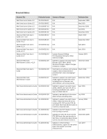 3
3 -
 4
4 -
 5
5 -
 6
6 -
 7
7 -
8
-
9
-
10
-
11
-
12
-
13
-
14
-
15
-
16
-
17
-
18
-
19
-
20
-
21
-
22
-
23
-
24
-
25
-
26
-
27
-
28
-
29
-
30
-
31
-
32
-
33
-
34
-
35
-
36
-
37
-
38
-
39
-
40
-
41
-
42
-
43
-
44
-
45
-
46
-
47
-
48
-
49
-
50
-
51
-
52
-
53
-
54
-
55
-
56
-
57
-
58
-
59
-
60
-
61
-
62
-
63
-
64
-
65
-
66
-
67
-
68
-
69
-
70
-
71
-
72
-
73
-
74
-
75
-
76
-
77
-
78
-
79
-
80
-
81
-
82
-
83
-
84
-
85
-
86
-
87
-
88
-
89
-
90
-
91
-
92
-
93
-
94
-
95
-
96
-
97
-
98
-
99
-
100
-
101
-
102
-
103
-
104
-
105
-
106
-
107
-
108
-
109
-
110
-
111
-
112
-
113
-
114
-
115
-
116
-
117
-
118
-
119
-
120
-
121
-
122
-
123
-
124
-
125
-
126
-
127
-
128
-
129
-
130
-
131
-
132
-
133
-
134
-
135
-
136
-
137
-
138
-
139
-
140
-
141
-
142
-
143
-
144
-
145
-
146
-
147
-
148
-
149
-
150
-
151
-
152
-
153
-
154
-
155
-
156
-
157
-
158
-
159
-
160
-
161
-
162
-
163
-
164
-
165
-
166
-
167
-
168
-
169
-
170
-
171
-
172
-
173
-
174
-
175
-
176
-
177
-
178
-
179
-
180
-
181
-
182
-
183
-
184
-
185
-
186
-
187
-
188
-
189
-
190
-
191
-
192
-
193
-
194
-
195
-
196
-
197
-
198
-
199
-
200
-
201
-
202
-
203
-
204
-
205
-
206
-
207
-
208
-
209
-
210
-
211
-
212
-
213
-
214
-
215
-
216
-
217
-
218
-
219
-
220
-
221
-
222
-
223
-
224
-
225
-
226
-
227
-
228
-
229
-
230
-
231
-
232
-
233
-
234
-
235
-
236
-
237
-
238
-
239
-
240
-
241
-
242
-
243
-
244
-
245
-
246
-
247
-
248
-
249
-
250
-
251
-
252
-
253
-
254
-
255
-
256
-
257
-
258
-
259
-
260
-
261
-
262
-
263
-
264
-
265
-
266
-
267
-
268
-
269
-
270
-
271
-
272
-
273
-
274
-
275
-
276
-
277
-
278
-
279
-
280
-
281
-
282
-
283
-
284
-
285
-
286
-
287
-
288
-
289
-
290
-
291
-
292
-
293
-
294
-
295
-
296
-
297
-
298
-
299
-
300
-
301
-
302
-
303
-
304
-
305
-
306
-
307
-
308
-
309
-
310
 |
 |

53-1001772-01
30 March 2010
®
DRAFT: BROCADE CONFIDENTIAL
Web Tools
Administrator’s Guide
Supporting Fabric OS v6.4.0