Dell PowerEdge R415 Hardware Owner's Manual - Page 127
Processors, Removing a Processor
 |
View all Dell PowerEdge R415 manuals
Add to My Manuals
Save this manual to your list of manuals |
Page 127 highlights
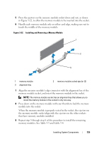
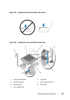
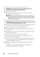
5 Press down and out on the ejectors on each end of the socket until the memory module pops out of the socket. See Figure 3-22. Handle each memory module only on either card edge, making sure not to touch the middle of the memory module. 6 Replace the system board shroud. See "Installing the System Board Shroud" on page 110. 7 Close the system. See "Closing the System" on page 83. Processors Removing a Processor CAUTION: Many repairs may only be done by a certified service technician. You should only perform troubleshooting and simple repairs as authorized in your product documentation, or as directed by the online or telephone service and support team. Damage due to servicing that is not authorized by Dell is not covered by your warranty. Read and follow the safety instructions that came with the product. 1 Prior to upgrading your system, download the latest system BIOS version from support.dell.com and follow the instructions included in the compressed download file to install the update on your system. 2 Turn off the system, including any attached peripherals, and disconnect the system from the electrical outlet. When disconnected from AC power, press and hold the power button for 3 seconds to fully drain the system of stored power prior to removing the cover. NOTE: It is recommended that you always use a static mat and static strap while working on components in the interior of the system. 3 Open the system. See "Opening the System" on page 82. 4 Remove the system board shroud. See "Removing the System Board Shroud" on page 109. WARNING: The heat sink and processor are hot to touch for some time after the system has been powered down. Allow the heat sink and processor to cool before handling them. CAUTION: Never remove the heat sink from a processor unless you intend to remove the processor. The heat sink is necessary to maintain proper thermal conditions. Installing System Components 127
-
 1
1 -
2
-
3
-
4
-
5
-
6
-
7
-
8
-
9
-
10
-
11
-
12
-
13
-
14
-
15
-
16
-
17
-
18
-
19
-
20
-
21
-
22
-
23
-
24
-
25
-
26
-
27
-
28
-
29
-
30
-
31
-
32
-
33
-
34
-
35
-
36
-
37
-
38
-
39
-
40
-
41
-
42
-
43
-
44
-
45
-
46
-
47
-
48
-
49
-
50
-
51
-
52
-
53
-
54
-
55
-
56
-
57
-
58
-
59
-
60
-
61
-
62
-
63
-
64
-
65
-
66
-
67
-
68
-
69
-
70
-
71
-
72
-
73
-
74
-
75
-
76
-
77
-
78
-
79
-
80
-
81
-
82
-
83
-
84
-
85
-
86
-
87
-
88
-
89
-
90
-
91
-
92
-
93
-
94
-
95
-
96
-
97
-
98
-
99
-
100
-
101
-
102
-
103
-
104
-
105
-
106
-
107
-
108
-
109
-
110
-
111
-
112
-
113
-
114
-
115
-
116
-
117
-
118
-
119
-
120
-
121
-
 122
122 -
 123
123 -
 124
124 -
 125
125 -
 126
126 -
 127
127 -
 128
128 -
 129
129 -
 130
130 -
 131
131 -
 132
132 -
133
-
134
-
135
-
136
-
137
-
138
-
139
-
140
-
141
-
142
-
143
-
144
-
145
-
146
-
147
-
148
-
149
-
150
-
151
-
152
-
153
-
154
-
155
-
156
-
157
-
158
-
159
-
160
-
161
-
162
-
163
-
164
-
165
-
166
-
167
-
168
-
169
-
170
-
171
-
172
-
173
-
174
-
175
-
176
-
177
-
178
-
179
-
180
-
181
-
182
-
183
-
184
-
185
-
186
-
187
-
188
 |
 |