Dell PowerEdge R415 Hardware Owner's Manual - Page 145
Remove the memory modules. See Removing Memory Modules on, Enterprise Card Optional
 |
View all Dell PowerEdge R415 manuals
Add to My Manuals
Save this manual to your list of manuals |
Page 145 highlights
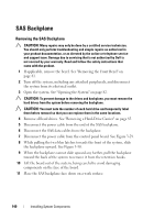
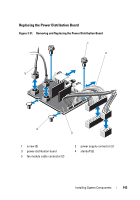
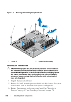
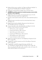
1 Turn off the system, including any attached peripherals, and disconnect the system from its electrical outlet. 2 Open the system. See "Opening the System" on page 82. 3 If applicable, remove the front bezel. See "Removing the Front Bezel" on page 81. 4 Remove the system board shroud. See "Removing the System Board Shroud" on page 109. 5 Remove the memory modules. See "Removing Memory Modules" on page 126. 6 Remove the expansion card and the integrated storage controller card. See "Removing an Expansion Card" on page 100 and "Removing the Integrated Storage Controller Card" on page 103. 7 Remove the expansion-card riser. See "Removing an Expansion-Card Riser" on page 105. 8 Remove the heat sinks and processors. See "Removing a Processor" on page 127. 9 If applicable, remove the optional iDRAC6 Enterprise card. See "iDRAC6 Enterprise Card (Optional)" on page 114. 10 If installed, remove the optional iDRAC6 Express card. See "iDRAC6 Express Card (Optional)" on page 112. 11 Disconnect all cables from the system board. 12 Remove the nine screws securing the system board to the chassis and then slide the system board assembly toward the front end of the chassis. CAUTION: Do not lift the system board assembly by grasping a memory module, processor, or other components. 13 Grasp the system board assembly by its edges and lift the assembly away from the chassis. See Figure 3-32. Installing System Components 145
-
 1
1 -
2
-
3
-
4
-
5
-
6
-
7
-
8
-
9
-
10
-
11
-
12
-
13
-
14
-
15
-
16
-
17
-
18
-
19
-
20
-
21
-
22
-
23
-
24
-
25
-
26
-
27
-
28
-
29
-
30
-
31
-
32
-
33
-
34
-
35
-
36
-
37
-
38
-
39
-
40
-
41
-
42
-
43
-
44
-
45
-
46
-
47
-
48
-
49
-
50
-
51
-
52
-
53
-
54
-
55
-
56
-
57
-
58
-
59
-
60
-
61
-
62
-
63
-
64
-
65
-
66
-
67
-
68
-
69
-
70
-
71
-
72
-
73
-
74
-
75
-
76
-
77
-
78
-
79
-
80
-
81
-
82
-
83
-
84
-
85
-
86
-
87
-
88
-
89
-
90
-
91
-
92
-
93
-
94
-
95
-
96
-
97
-
98
-
99
-
100
-
101
-
102
-
103
-
104
-
105
-
106
-
107
-
108
-
109
-
110
-
111
-
112
-
113
-
114
-
115
-
116
-
117
-
118
-
119
-
120
-
121
-
122
-
123
-
124
-
125
-
126
-
127
-
128
-
129
-
130
-
131
-
132
-
133
-
134
-
135
-
136
-
137
-
138
-
139
-
 140
140 -
 141
141 -
 142
142 -
 143
143 -
 144
144 -
 145
145 -
 146
146 -
 147
147 -
 148
148 -
 149
149 -
 150
150 -
151
-
152
-
153
-
154
-
155
-
156
-
157
-
158
-
159
-
160
-
161
-
162
-
163
-
164
-
165
-
166
-
167
-
168
-
169
-
170
-
171
-
172
-
173
-
174
-
175
-
176
-
177
-
178
-
179
-
180
-
181
-
182
-
183
-
184
-
185
-
186
-
187
-
188
 |
 |
