Dell PowerEdge R415 Hardware Owner's Manual - Page 135
Control Panel Assembly, Removing the Control Panel Assembly
 |
View all Dell PowerEdge R415 manuals
Add to My Manuals
Save this manual to your list of manuals |
Page 135 highlights
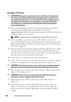
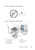
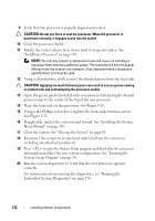
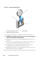
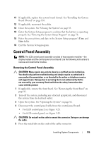
11 If applicable, replace the system board shroud. See "Installing the System Board Shroud" on page 110. 12 If applicable, reconnect the cables. 13 Close the system. See "Closing the System" on page 83. 14 Enter the System Setup program to confirm that the battery is operating properly. See "Entering the System Setup Program" on page 58. 15 Enter the correct time and date in the System Setup program's Time and Date fields. 16 Exit the System Setup program. Control Panel Assembly NOTE: The LCD control panel assembly consists of two separate modules-the display module and the control panel circuit board. Use the following instructions to remove and install either module. Removing the Control Panel Assembly CAUTION: Many repairs may only be done by a certified service technician. You should only perform troubleshooting and simple repairs as authorized in your product documentation, or as directed by the online or telephone service and support team. Damage due to servicing that is not authorized by Dell is not covered by your warranty. Read and follow the safety instructions that came with the product 1 If applicable, remove the front bezel. See "Removing the Front Bezel" on page 81. 2 Turn off the system, including any attached peripherals, and disconnect the system from its electrical outlet. 3 Open the system. See "Opening the System" on page 82. 4 Disconnect the control panel cable from the control panel board. • For LED control panel, see Figure 3-28. • For LCD control panel, see Figure 3-29. CAUTION: Do not pull on the cable to unseat the connector. Doing so can damage the cable. 5 Press the metal tabs on the ends of the cable connector. Installing System Components 135
-
 1
1 -
2
-
3
-
4
-
5
-
6
-
7
-
8
-
9
-
10
-
11
-
12
-
13
-
14
-
15
-
16
-
17
-
18
-
19
-
20
-
21
-
22
-
23
-
24
-
25
-
26
-
27
-
28
-
29
-
30
-
31
-
32
-
33
-
34
-
35
-
36
-
37
-
38
-
39
-
40
-
41
-
42
-
43
-
44
-
45
-
46
-
47
-
48
-
49
-
50
-
51
-
52
-
53
-
54
-
55
-
56
-
57
-
58
-
59
-
60
-
61
-
62
-
63
-
64
-
65
-
66
-
67
-
68
-
69
-
70
-
71
-
72
-
73
-
74
-
75
-
76
-
77
-
78
-
79
-
80
-
81
-
82
-
83
-
84
-
85
-
86
-
87
-
88
-
89
-
90
-
91
-
92
-
93
-
94
-
95
-
96
-
97
-
98
-
99
-
100
-
101
-
102
-
103
-
104
-
105
-
106
-
107
-
108
-
109
-
110
-
111
-
112
-
113
-
114
-
115
-
116
-
117
-
118
-
119
-
120
-
121
-
122
-
123
-
124
-
125
-
126
-
127
-
128
-
129
-
 130
130 -
 131
131 -
 132
132 -
 133
133 -
 134
134 -
 135
135 -
 136
136 -
 137
137 -
 138
138 -
 139
139 -
 140
140 -
141
-
142
-
143
-
144
-
145
-
146
-
147
-
148
-
149
-
150
-
151
-
152
-
153
-
154
-
155
-
156
-
157
-
158
-
159
-
160
-
161
-
162
-
163
-
164
-
165
-
166
-
167
-
168
-
169
-
170
-
171
-
172
-
173
-
174
-
175
-
176
-
177
-
178
-
179
-
180
-
181
-
182
-
183
-
184
-
185
-
186
-
187
-
188
 |
 |
