Dell PowerEdge SC1435 Rack Installation Guide - Page 12
Installation Tasks, Removing the Rack Doors, Marking the Rack - weight
 |
View all Dell PowerEdge SC1435 manuals
Add to My Manuals
Save this manual to your list of manuals |
Page 12 highlights
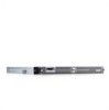
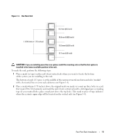
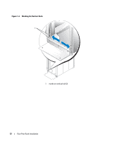
Installation Tasks Installing a rack kit involves performing the following tasks (described in detail in subsequent sections) in their numbered order: 1 Removing the rack doors 2 Marking the rack 3 Configuring the sliding rail assemblies (sliding rail kits only) 4 Installing chassis static rail modules (static rail kits only) 5 Installing the mounting rails in the rack 6 Installing the system in the rack 7 Installing the tray and cable-management arm (sliding rail kits only) 8 Routing cables 9 Replacing the rack doors Removing the Rack Doors See the procedures for removing doors in the documentation provided with your rack cabinet. CAUTION: Because of the size and weight of the rack cabinet doors, never attempt to remove or install them by yourself. CAUTION: Store the two doors where they will not injure someone if the doors accidently fall over. Marking the Rack For a 1-U system, you must allow 1 U (44 mm, or 1.75 inches) of vertical space for each system you install in the rack. Rack cabinets that meet EIA-310 standards have an alternating pattern of three holes per rack unit with center-to-center hole spacing (beginning at the top hole of a 1-U space) of 15.9 mm, 15.9 mm, and 12.7 mm (0.625 inch, 0.625 inch, and 0.5 inch) for the front and back vertical rails (see Figure 1-3). Rack cabinets may have round or square holes. NOTE: The vertical rails may be marked by horizontal lines and numbers in 1-U increments. If you want, you can make a note of the number marking on the rack's vertical rail. It is not necessary to mark or place tape on the rack. 10 Four-Post Rack Installation
-
 1
1 -
2
-
3
-
4
-
5
-
6
-
 7
7 -
 8
8 -
 9
9 -
 10
10 -
 11
11 -
 12
12 -
 13
13 -
 14
14 -
 15
15 -
 16
16 -
 17
17 -
18
-
19
-
20
-
21
-
22
-
23
-
24
-
25
-
26
-
27
-
28
-
29
-
30
-
31
-
32
-
33
-
34
-
35
-
36
-
37
-
38
-
39
-
40
-
41
-
42
-
43
-
44
-
45
-
46
-
47
-
48
-
49
-
50
-
51
-
52
-
53
-
54
-
55
-
56
-
57
-
58
-
59
-
60
-
61
-
62
-
63
-
64
-
65
-
66
-
67
-
68
-
69
-
70
-
71
-
72
-
73
-
74
-
75
-
76
-
77
-
78
-
79
-
80
-
81
-
82
-
83
-
84
-
85
-
86
-
87
-
88
-
89
-
90
-
91
-
92
-
93
-
94
-
95
-
96
-
97
-
98
-
99
-
100
-
101
-
102
-
103
-
104
-
105
-
106
-
107
-
108
-
109
-
110
-
111
-
112
-
113
-
114
-
115
-
116
-
117
-
118
-
119
-
120
-
121
-
122
-
123
-
124
-
125
-
126
-
127
-
128
-
129
-
130
-
131
-
132
-
133
-
134
-
135
-
136
-
137
-
138
-
139
-
140
-
141
-
142
-
143
-
144
-
145
-
146
-
147
-
148
-
149
-
150
-
151
-
152
-
153
-
154
-
155
-
156
-
157
-
158
-
159
-
160
-
161
-
162
-
163
-
164
-
165
-
166
-
167
-
168
-
169
-
170
-
171
-
172
-
173
-
174
-
175
-
176
-
177
-
178
-
179
-
180
-
181
-
182
-
183
-
184
-
185
-
186
-
187
-
188
-
189
-
190
-
191
-
192
-
193
-
194
-
195
-
196
-
197
-
198
-
199
-
200
-
201
-
202
 |
 |