Dell PowerEdge SC1435 Rack Installation Guide - Page 26
Routing Cables, Getting Started Guide, Hardware Owner's, Manual
 |
View all Dell PowerEdge SC1435 manuals
Add to My Manuals
Save this manual to your list of manuals |
Page 26 highlights
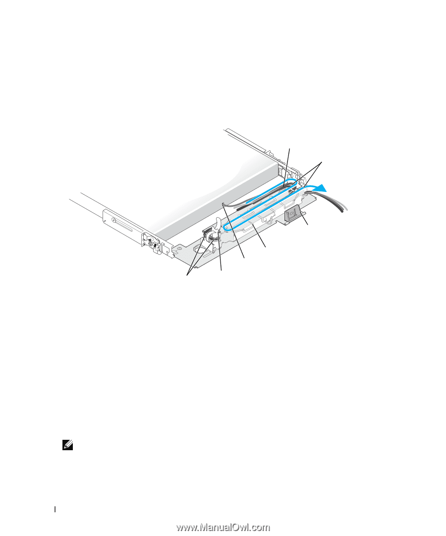
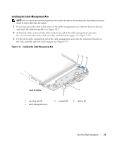
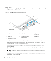
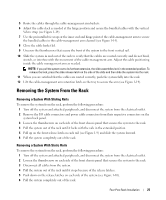
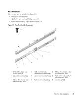
Routing Cables 1 Open the wire cable basket lid on the top of the cable-management arm, to enable cables to be routed within the arms (see Figure 1-14). Figure 1-14. Routing Cables on the Cable-Management Arm 1 2 3 back of system 4 5 6 7 1 cable-management arm 4 basket lid 7 preinstalled tie wraps 2 preinstalled tie wraps 5 system status-indicator cable connector 3 cable-management arm retention latch 6 Velcro strap 2 If applicable, connect the system status-indicator cable to its connector on the system back panel. Route the system status-indicator cable through the cable-management arm and insert the LED end into the slot on the end of the cable-management arm. 3 Attach the I/O cable connectors and power cable connectors to their respective connectors on the system back panel. For details on cable connections, see your system's Getting Started Guide or Hardware Owner's Manual. NOTE: Use the strain-relief loops on the back of the power supplies to provide strain relief for the power cables. 4 Using the tie-wraps provided in the rack kit, bundle the cables together so that they do not interfere with adjacent systems in the rack. 24 Four-Post Rack Installation
-
 1
1 -
2
-
3
-
4
-
5
-
6
-
7
-
8
-
9
-
10
-
11
-
12
-
13
-
14
-
15
-
16
-
17
-
18
-
19
-
20
-
 21
21 -
 22
22 -
 23
23 -
 24
24 -
 25
25 -
 26
26 -
 27
27 -
 28
28 -
 29
29 -
 30
30 -
 31
31 -
32
-
33
-
34
-
35
-
36
-
37
-
38
-
39
-
40
-
41
-
42
-
43
-
44
-
45
-
46
-
47
-
48
-
49
-
50
-
51
-
52
-
53
-
54
-
55
-
56
-
57
-
58
-
59
-
60
-
61
-
62
-
63
-
64
-
65
-
66
-
67
-
68
-
69
-
70
-
71
-
72
-
73
-
74
-
75
-
76
-
77
-
78
-
79
-
80
-
81
-
82
-
83
-
84
-
85
-
86
-
87
-
88
-
89
-
90
-
91
-
92
-
93
-
94
-
95
-
96
-
97
-
98
-
99
-
100
-
101
-
102
-
103
-
104
-
105
-
106
-
107
-
108
-
109
-
110
-
111
-
112
-
113
-
114
-
115
-
116
-
117
-
118
-
119
-
120
-
121
-
122
-
123
-
124
-
125
-
126
-
127
-
128
-
129
-
130
-
131
-
132
-
133
-
134
-
135
-
136
-
137
-
138
-
139
-
140
-
141
-
142
-
143
-
144
-
145
-
146
-
147
-
148
-
149
-
150
-
151
-
152
-
153
-
154
-
155
-
156
-
157
-
158
-
159
-
160
-
161
-
162
-
163
-
164
-
165
-
166
-
167
-
168
-
169
-
170
-
171
-
172
-
173
-
174
-
175
-
176
-
177
-
178
-
179
-
180
-
181
-
182
-
183
-
184
-
185
-
186
-
187
-
188
-
189
-
190
-
191
-
192
-
193
-
194
-
195
-
196
-
197
-
198
-
199
-
200
-
201
-
202
 |
 |