Dell PowerEdge SC1435 Rack Installation Guide - Page 13
with a horizontal line on some rack cabinets-see
 |
View all Dell PowerEdge SC1435 manuals
Add to My Manuals
Save this manual to your list of manuals |
Page 13 highlights
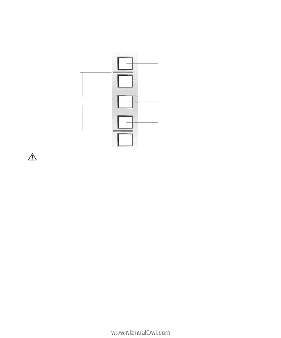
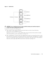
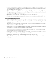
Figure 1-3. One Rack Unit 1 U (44 mm or 1.75 inches) 12.7 mm (0.5 inch) 15.9 mm (0.625 inch) 15.9 mm (0.625 inch) 12.7 mm (0.5 inch) CAUTION: If you are installing more than one system, install the mounting rails so that the first system is installed in the lowest available position in the rack. To mark the rack, perform the following steps: 1 Place a mark (or tape) on the rack's front vertical rails where you want to locate the bottom of the system you are installing in the rack. The bottom of each 1-U space is at the middle of the narrowest metal area between holes (marked with a horizontal line on some rack cabinets-see Figure 1-4). 2 Place a mark 44 mm (1.75 inches) above the original mark you made (or count up three holes in a rack that meets EIA-310 standards) and mark the rack's front vertical rails with a felt-tipped pen or masking tape (if you counted holes, place a mark just above the top hole). This mark or piece of tape indicates where the system's upper edge will be located on the vertical rails (see Figure 1-4). Four-Post Rack Installation 11
-
 1
1 -
2
-
3
-
4
-
5
-
6
-
7
-
 8
8 -
 9
9 -
 10
10 -
 11
11 -
 12
12 -
 13
13 -
 14
14 -
 15
15 -
 16
16 -
 17
17 -
 18
18 -
19
-
20
-
21
-
22
-
23
-
24
-
25
-
26
-
27
-
28
-
29
-
30
-
31
-
32
-
33
-
34
-
35
-
36
-
37
-
38
-
39
-
40
-
41
-
42
-
43
-
44
-
45
-
46
-
47
-
48
-
49
-
50
-
51
-
52
-
53
-
54
-
55
-
56
-
57
-
58
-
59
-
60
-
61
-
62
-
63
-
64
-
65
-
66
-
67
-
68
-
69
-
70
-
71
-
72
-
73
-
74
-
75
-
76
-
77
-
78
-
79
-
80
-
81
-
82
-
83
-
84
-
85
-
86
-
87
-
88
-
89
-
90
-
91
-
92
-
93
-
94
-
95
-
96
-
97
-
98
-
99
-
100
-
101
-
102
-
103
-
104
-
105
-
106
-
107
-
108
-
109
-
110
-
111
-
112
-
113
-
114
-
115
-
116
-
117
-
118
-
119
-
120
-
121
-
122
-
123
-
124
-
125
-
126
-
127
-
128
-
129
-
130
-
131
-
132
-
133
-
134
-
135
-
136
-
137
-
138
-
139
-
140
-
141
-
142
-
143
-
144
-
145
-
146
-
147
-
148
-
149
-
150
-
151
-
152
-
153
-
154
-
155
-
156
-
157
-
158
-
159
-
160
-
161
-
162
-
163
-
164
-
165
-
166
-
167
-
168
-
169
-
170
-
171
-
172
-
173
-
174
-
175
-
176
-
177
-
178
-
179
-
180
-
181
-
182
-
183
-
184
-
185
-
186
-
187
-
188
-
189
-
190
-
191
-
192
-
193
-
194
-
195
-
196
-
197
-
198
-
199
-
200
-
201
-
202
 |
 |