Dell PowerStore 9000T EMC PowerStore Installation and Service Guide - Page 82
If the I/O module and network cables are not already labeled
 |
View all Dell PowerStore 9000T manuals
Add to My Manuals
Save this manual to your list of manuals |
Page 82 highlights
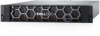
NOTE: If the I/O module and network cables are not already labeled, label them clearly for reconnecting later. Figure 104. Removing the power cable 2. Disconnect the network and all other cables from the back of the I/O modules and network ports on the node. NOTE: Do not remove any cables from the other node. 3. Pull the orange release trigger while gently pushing in on the node. The hook disengages from the locking mechanism, and the release tab slides out. NOTE: The node comes completely out of the chassis. Be prepared to support the node to avoid dropping it. Figure 105. Disengaging the locking mechanism 4. Use the release handle to pull the node outward enough to grasp the sides with both hands. Then, with both hands supporting the node, pull the node fully out of the enclosure. 82 Base enclosure service procedures
-
 1
1 -
2
-
3
-
4
-
5
-
6
-
7
-
8
-
9
-
10
-
11
-
12
-
13
-
14
-
15
-
16
-
17
-
18
-
19
-
20
-
21
-
22
-
23
-
24
-
25
-
26
-
27
-
28
-
29
-
30
-
31
-
32
-
33
-
34
-
35
-
36
-
37
-
38
-
39
-
40
-
41
-
42
-
43
-
44
-
45
-
46
-
47
-
48
-
49
-
50
-
51
-
52
-
53
-
54
-
55
-
56
-
57
-
58
-
59
-
60
-
61
-
62
-
63
-
64
-
65
-
66
-
67
-
68
-
69
-
70
-
71
-
72
-
73
-
74
-
75
-
76
-
 77
77 -
 78
78 -
 79
79 -
 80
80 -
 81
81 -
 82
82 -
 83
83 -
 84
84 -
 85
85 -
 86
86 -
 87
87 -
88
-
89
-
90
-
91
-
92
-
93
-
94
-
95
-
96
-
97
-
98
-
99
-
100
-
101
-
102
-
103
-
104
-
105
-
106
-
107
-
108
-
109
-
110
-
111
-
112
-
113
-
114
-
115
-
116
-
117
-
118
-
119
-
120
-
121
-
122
-
123
-
124
-
125
-
126
-
127
-
128
-
129
 |
 |
