Dell PowerVault 110T LTO3 User Guide - Page 15
Loading Device Drivers - powervault lto 3 driver
 |
View all Dell PowerVault 110T LTO3 manuals
Add to My Manuals
Save this manual to your list of manuals |
Page 15 highlights
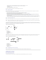
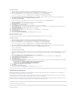
l Out of copy rooms to avoid toner and paper dust. Do not store paper supplies next to any unit. l Away from moving air, such as doorways, open windows, fans, and air conditioners. l Off the floor. l In a horizontal position. l Where the tape cartridge can easily be inserted. The tape drive should not be stacked. Do not place anything on top of the unit. Step 3 - Connecting Power An external Dell PowerVault 110T LTO-3 Tape Drive will operate using any voltage in the range 100-240 volts (50-60 Hz). No adjustment is needed. To connect your drive to the power supply, proceed as follows: 1. Ensure that the power on/off button is set to off by pressing it (See number 4 in Figure 7). 2. Plug the power cable securely into the socket on the rear panel of the drive. (See number 2 in Figure 7.) 3. Plug the other end of the power cable into a grounded power outlet. 4. Because the tape drive may not complete the Power-On Self-Test (POST) without SCSI termination, ensure that the terminator (or SCSI bus with termination) is connected to one of the two SCSI connectors at the rear of the unit (See number 3 in Figure 7). 5. Power on the tape drive by pressing the power on/off button (See number 4 in Figure 7. The tape drive runs the POST, which checks all hardware except the drive head. 6. Write the model name, product number, serial number, SCSI ID, and service tag number (external drives only) of your drive somewhere safe for future reference. The model name is on the front of the drive and the product service tag, and serial numbers are on a label on the bottom of the drive. Step 4 - Connecting the SCSI Cable Perform a normal system shutdown and turn off the system and any connected peripherals. Ensure that the tape drive is plugged into an electrical outlet. NOTICE: To avoid damaging the system or tape drive, ensure that both are powered off while you attach the SCSI cable. For optimum performance, we recommend that your tape drive is installed on a dedicated SCSI bus. If the tape drive is the only device on the SCSI bus, attach one end of the SCSI cable to the system. Attach the other end of the SCSI cable to either SCSI connector on the rear panel of the tape drive (see number 3 in Figure 7) and secure it by tightening the screws. The cable can be up to 25 m (82 ft) long when the tape drive is the only device on the bus. This configuration is shown in Figure 8. Figure 8. Connecting One SCSI Device 1. Tape drive 2. SCSI connectors 3. Terminator 4. SCSI bus cable 5. SCSI host adapter card 6. System If the tape drive is one of multiple devices on the SCSI bus, connect the SCSI cable to the next device on the bus, move the terminator to the last device on the bus, and then issue the system command to resume operation. This configuration is shown in Figure 9. The cable can be up to 12 m (39 ft) long. Figure 9. Connecting Multiple SCSI Devices 1. Tape drive 2. SCSI connectors 3. Terminator 4. SCSI bus cable 5. SCSI host adapter card 6. System 7. Another device Step 5 - Configuring the Tape Drive to the Host Power on the tape drive. Refer to your system and application software manuals to configure the tape drive for use. Loading Device Drivers Microsoft® Windows® 2000 This section describes how to install, remove, and disable the Microsoft Windows 2000 Device Drivers for the tape drive.
-
 1
1 -
2
-
3
-
4
-
5
-
6
-
7
-
8
-
9
-
 10
10 -
 11
11 -
 12
12 -
 13
13 -
 14
14 -
 15
15 -
 16
16 -
 17
17 -
 18
18 -
 19
19 -
 20
20 -
21
-
22
-
23
-
24
-
25
-
26
-
27
-
28
-
29
-
30
-
31
 |
 |
