Dell Vostro 1710 Service Manual - Page 10
Removing the Processor Module, Replacing the Processor Thermal, Cooling Assembly, Replacing the Fan
 |
View all Dell Vostro 1710 manuals
Add to My Manuals
Save this manual to your list of manuals |
Page 10 highlights
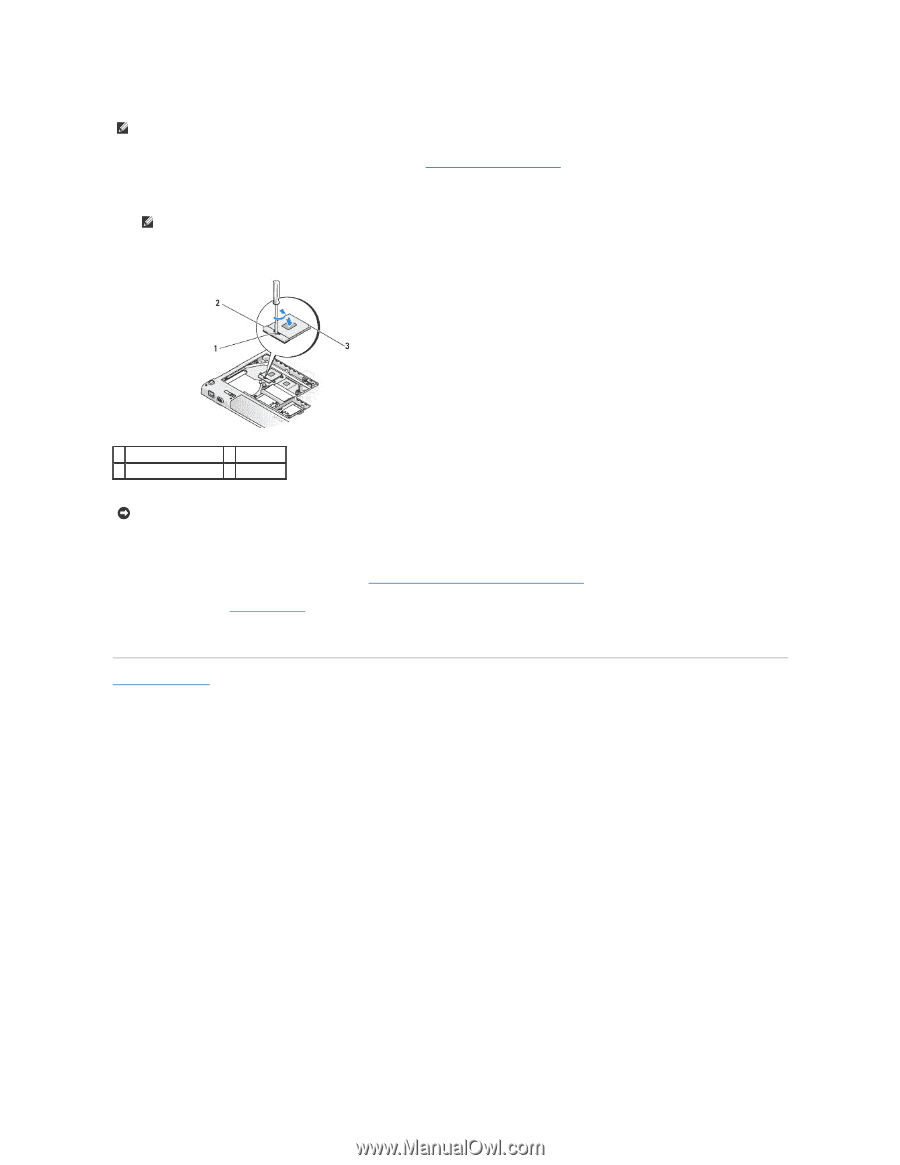
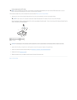
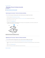
to the microprocessor and ZIF socket. NOTE: If you are installing a new processor, you will receive a new thermal-cooling assembly which will include an affixed thermal pad, or you will receive a new thermal pad along with a tech sheet to illustrate proper installation. This procedure assumes that you have completed the removal procedure Removing the Processor Module. 1. Align the pin-1 corner of the processor module with the pin-1 corner of the ZIF socket, then insert the processor module. NOTE: The pin-1 corner of the processor module has a triangle that aligns with the triangle on the pin-1 corner of the ZIF socket. When the processor module is properly seated, all four corners are aligned at the same height. If one or more corners of the module are higher than the others, the module is not seated properly. 1 ZIF-socket cam screw 2 ZIF socket 3 pin-1 corner NOTICE: To avoid damage to the processor, hold the screwdriver so that it is perpendicular to the processor when turning the cam screw. 2. Tighten the ZIF socket by turning the cam screw clockwise to secure the processor module to the system board. 3. Replace the processor thermal-cooling assembly (see Replacing the Processor Thermal-Cooling Assembly). 4. Replace the fan (see Replacing the Fan). 5. Replace the memory cover and tighten the eight screws that secure the memory cover. Back to Contents Page
-
 1
1 -
2
-
3
-
4
-
 5
5 -
 6
6 -
 7
7 -
 8
8 -
 9
9 -
 10
10 -
 11
11 -
 12
12 -
 13
13 -
 14
14 -
 15
15 -
16
-
17
-
18
-
19
-
20
-
21
-
22
-
23
-
24
-
25
-
26
-
27
-
28
-
29
-
30
-
31
-
32
-
33
-
34
-
35
-
36
-
37
-
38
-
39
-
40
-
41
-
42
-
43
-
44
-
45
-
46
-
47
-
48
-
49
-
50
-
51
-
52
-
53
-
54
-
55
-
56
-
57
-
58
 |
 |