Dell Vostro 1710 Service Manual - Page 19
Camera and Microphone Assembly
 |
View all Dell Vostro 1710 manuals
Add to My Manuals
Save this manual to your list of manuals |
Page 19 highlights
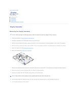
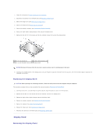
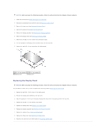
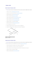
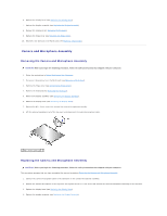
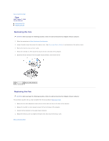
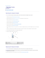
6. Replace the display bezel (see Replacing the Display Bezel). 7. Replace the display assembly (see Replacing the Display Assembly). 8. Replace the keyboard (see Replacing the Keyboard). 9. Replace the hinge cover (see Replacing the Hinge Cover). 10. Reconnect the antenna to the WLAN card (see Replacing a WLAN Card). Camera and Microphone Assembly Removing the Camera and Microphone Assembly CAUTION: Before you begin the following procedure, follow the safety instructions that shipped with your computer. 1. Follow the instructions in Before Working on Your Computer. 2. Disconnect the antenna from the WLAN card (see Removing a WLAN Card). 3. Remove the hinge cover (see Removing the Hinge Cover). 4. Remove the keyboard (see Removing the Keyboard). 5. Remove the display assembly (see Removing the Display Assembly). 6. Remove the display bezel (see Removing the Display Bezel). 7. Remove the M2 x 3-mm screw that secures the camera/microphone assembly. 8. Lift the camera/microphone out of the top cover and disconnect the camera/microphone cable. 1 M2 x 3-mm screw (1) Replacing the Camera and Microphone Assembly CAUTION: Before you begin the following procedure, follow the safety instructions that shipped with your computer. This procedure assumes that you have completed the removal procedure Removing the Camera and Microphone Assembly. 1. Connect the camera/microphone cable to the connector on the camera/microphone assembly. 2. Position the camera/microphone in the top cover and replace the M2 x 3- mm screw that secures the camera/microphone assembly to the top cover. 3. Replace the display bezel (see Replacing the Display Bezel). 4. Replace the display assembly (see Replacing the Display Assembly).
-
 1
1 -
2
-
3
-
4
-
5
-
6
-
7
-
8
-
9
-
10
-
11
-
12
-
13
-
 14
14 -
 15
15 -
 16
16 -
 17
17 -
 18
18 -
 19
19 -
 20
20 -
 21
21 -
 22
22 -
 23
23 -
 24
24 -
25
-
26
-
27
-
28
-
29
-
30
-
31
-
32
-
33
-
34
-
35
-
36
-
37
-
38
-
39
-
40
-
41
-
42
-
43
-
44
-
45
-
46
-
47
-
48
-
49
-
50
-
51
-
52
-
53
-
54
-
55
-
56
-
57
-
58
 |
 |