Dell Vostro 1710 Service Manual - Page 21
Removing the Fan, Replacing the Fan
 |
View all Dell Vostro 1710 manuals
Add to My Manuals
Save this manual to your list of manuals |
Page 21 highlights
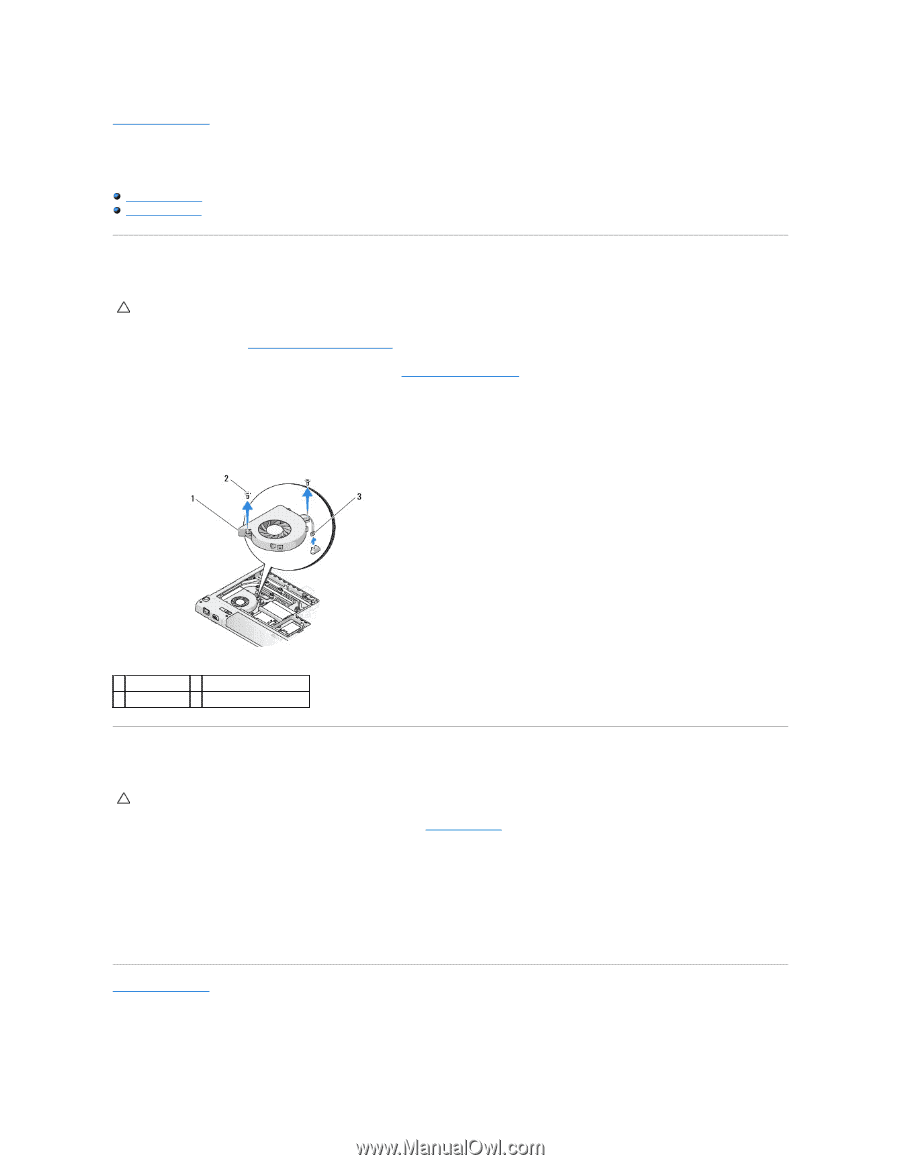
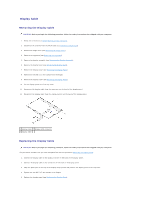
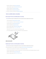
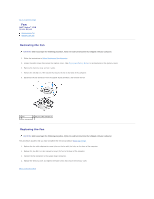
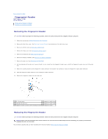
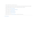
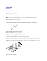
Back to Contents Page Fan Dell™ Vostro™ 1710 Service Manual Removing the Fan Replacing the Fan Removing the Fan CAUTION: Before you begin the following procedure, follow the safety instructions that shipped with your computer. 1. Follow the instructions in Before Working on Your Computer. 2. Loosen the eight screws that secure the memory cover. (See Removing a Memory Module for an illustration of the memory cover.) 3. Remove the memory cover and set it aside. 4. Remove the two M2.0 x 3-mm screws that secure the fan to the base of the computer. 5. Disconnect the fan connector from the system board connector, and remove the fan. 1 fan 2 M2.0 x 3-mm screws (2) 3 fan connector Replacing the Fan CAUTION: Before you begin the following procedure, follow the safety instructions that shipped with your computer. This procedure assumes that you have completed the removal procedure Removing the Fan. 1. Replace the fan while aligning the screw holes on the fan with the holes on the base of the computer. 2. Replace the two M2.0 x 3-mm screws to secure the fan to the base of the computer. 3. Connect the fan connector to the system board connector. 4. Replace the memory cover and tighten the eight screws that secure the memory cover. Back to Contents Page
-
 1
1 -
2
-
3
-
4
-
5
-
6
-
7
-
8
-
9
-
10
-
11
-
12
-
13
-
14
-
15
-
 16
16 -
 17
17 -
 18
18 -
 19
19 -
 20
20 -
 21
21 -
 22
22 -
 23
23 -
 24
24 -
 25
25 -
 26
26 -
27
-
28
-
29
-
30
-
31
-
32
-
33
-
34
-
35
-
36
-
37
-
38
-
39
-
40
-
41
-
42
-
43
-
44
-
45
-
46
-
47
-
48
-
49
-
50
-
51
-
52
-
53
-
54
-
55
-
56
-
57
-
58
 |
 |