Dell W-7030 Controller Installation Guide - Page 11
Power, Status, and Peered LEDs, LCD Panel, Function, Indicator
 |
View all Dell W-7030 manuals
Add to My Manuals
Save this manual to your list of manuals |
Page 11 highlights
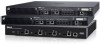
Figure 11 Ports, LEDs, and LCD Panel 6 STAT LAICNTK/ 4 6 STAT 7 5 7 POWER STATUS PEERED CONSOLE MENU ENTER Power, Status, and Peered LEDs The front panel also includes Power, Status, and Peered LEDs that provide basic monitoring of the overall status of the W-7030 controller. See Figure 11. Table 7 Power, Status, and Peered LEDs LED Function Indicator Status Power System Power Status System Status Peered Reserved for future use Green (Solid) Off Green (Solid) Green (Blinking) Amber (Blinking) Amber (Solid) Off N/A Power On Power Off Operational Device is loading software Major Alarm Critical Alarm No power N/A LCD Panel The W-7030 controller is equipped with an LCD panel (see Figure 11) that displays information about the controller's status, and provides a menu that allows basic operations such as initial setup and reboot. The LCD panel displays two lines of text with a maximum of 16 characters per line. When using the LCD panel, the active line is indicated by an arrow next to the first letter. The LCD panel is operated using the two navigation buttons to the right of the screen. Menu: Allows navigation through the menus of the LCD panel. Enter: Confirms and executes the action currently displayed on the LCD panel. Dell Networking W-7030 Controller | Installation Guide W-7030 Controller | 19
-
 1
1 -
2
-
3
-
4
-
5
-
 6
6 -
 7
7 -
 8
8 -
 9
9 -
 10
10 -
 11
11 -
 12
12 -
 13
13 -
 14
14 -
 15
15 -
 16
16 -
17
-
18
-
19
-
20
-
21
-
22
-
23
-
24
-
25
-
26
-
27
-
28
 |
 |
