Dell W-7030 Controller Installation Guide - Page 8
W-7030 Components, Table 3
 |
View all Dell W-7030 manuals
Add to My Manuals
Save this manual to your list of manuals |
Page 8 highlights
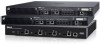
W-7030 Components This section introduces the different components of the W-7030 controller, and specifies their locations in the controller. Figure 8 shows the front panel of the W-7030 controller and Figure 9 shows the back panel of the W-7030 controller. Figure 8 Front Panel of the W-7030 Controller Access ports Power, Status, and Peered LEDs LCD Menu button LINK/ ACT 0 2 STAT LINK/ ACT 0 2 STAT LINK/ ACT 4 6 STAT LINK/ ACT 4 6 STAT POWER STATUS PEERED MENU ENTER 1 3 1 3 5 7 5 7 CONSOLE USB interface Console port Enter button Mini-USB console port Figure 9 Back Panel of the W-7030 Controller AC in Kensington lock Grounding point The following table lists the different components of the W-7030 controller: Table 3 W-7030 Controller Components Component Description Access Ports Power, Status, and Peered LEDs LCD Menu Button Enter Button USB Interface Console Port Mini-USB Console Port AC in Kensington lock 8 x dual media ports (10/100/1000BASE-T and 1000BASE-X) Provides basic monitoring of the controller Allows configuration of LED behavior and other basic operations Allows selection of the LCD screen menu Allows execution of actions on the LCD Screen 1 x USB 2.0, USB storage device can be used to save and upload configurations RJ-45 serial console access port Provides console access for direct local access AC power connector Kensington lock security port 16 | W-7030 Controller Dell Networking W-7030 Controller | Installation Guide
-
 1
1 -
2
-
 3
3 -
 4
4 -
 5
5 -
 6
6 -
 7
7 -
 8
8 -
 9
9 -
 10
10 -
 11
11 -
 12
12 -
 13
13 -
14
-
15
-
16
-
17
-
18
-
19
-
20
-
21
-
22
-
23
-
24
-
25
-
26
-
27
-
28
 |
 |
