Dell W-7200 PowerConnect Series Controller Installation Guide - Page 12
Callout, Component, Description, Function/Menu Options, Displays, Table 8
 |
View all Dell W-7200 manuals
Add to My Manuals
Save this manual to your list of manuals |
Page 12 highlights
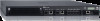
Figure 3 LCD Panel 1 POWER STATUS PEERED MENU 2 ENTER 3 7200_03 CONSOLE Table 8 LCD Panel Components Callout Component 1 LCD Screen 2 Menu Button 3 Enter Button Description Used to configure LCD behavior and other basic operations Used to select the LCD screen menu Used to execute actions on the LCD Screen The LCD panel is operated using the two navigation buttons to the left of the screen. Menu: Allows you to navigate through the menus of the LCD panel. Enter: Confirms and executes the action currently displayed on the LCD panel. The LCD has four modes: Boot: Displays the boot up status. LED Mode: Displays the mode that the STATUS LED is in. Status: Displays the status of different components of the W-7200 controller, including Power Supplies and ArubaOS version. Maintenance: Allows you to execute some basic operations of the W-7200 controller such as uploading an image or rebooting the system. Table 9 LCD Panel Mode: Boot Function/Menu Options Displays Displays boot status "Booting Dell PowerConnect W-ArubaOS... The LED mode menu allows you to choose what information is communicated by the LEDs on each port. Refer to Table 6 on page 10 for descriptions of the LED behavior of each mode. Table 10 LCD Panel Mode: LED Mode Function/Menu Options Displays Administrative Duplex LED MODE: ADM - displays whether the port is administratively enabled or disabled. LED MODE: DPX - displays the duplex mode of the port. 12 | Dell PowerConnect W-7200 Controller Dell PowerConnect W-7200 Series Controller | Installation Guide
-
 1
1 -
2
-
3
-
4
-
5
-
6
-
 7
7 -
 8
8 -
 9
9 -
 10
10 -
 11
11 -
 12
12 -
 13
13 -
 14
14 -
 15
15 -
 16
16 -
 17
17 -
18
-
19
-
20
-
21
-
22
-
23
-
24
-
25
-
26
-
27
-
28
-
29
-
30
-
31
-
32
 |
 |
