Dell XPS M1530 M1530 XPS M1530 Service Manual - Page 33
Update the BIOS using a flash BIOS-update program CD. See Flashing
 |
View all Dell XPS M1530 M1530 manuals
Add to My Manuals
Save this manual to your list of manuals |
Page 33 highlights
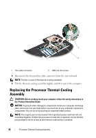
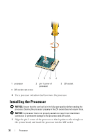
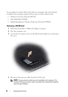
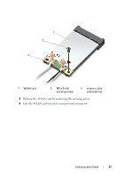
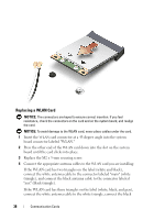
When the processor is correctly seated, all four corners are aligned at the same height. If one or more corners of the processor are higher than the others, the processor is not seated correctly. NOTICE: To prevent intermittent contact between the ZIF-socket cam screw and the processor when removing or replacing the processor, press to apply slight pressure to the center of the processor while turning the cam screw. 2 Tighten the ZIF socket by turning the cam screw clockwise to secure the processor to the system board. 3 Peel the backing off the thermal cooling pad and adhere the pad to the portion of the thermal-cooling assembly that covers the processor. 4 Replace the processor thermal-cooling assembly (see "Replacing the Processor Thermal-Cooling Assembly" on page 28). 5 Replace the module cover. 6 Update the BIOS using a flash BIOS-update program CD. See ("Flashing the BIOS" on page 113). Processor 33
-
 1
1 -
2
-
3
-
4
-
5
-
6
-
7
-
8
-
9
-
10
-
11
-
12
-
13
-
14
-
15
-
16
-
17
-
18
-
19
-
20
-
21
-
22
-
23
-
24
-
25
-
26
-
27
-
 28
28 -
 29
29 -
 30
30 -
 31
31 -
 32
32 -
 33
33 -
 34
34 -
 35
35 -
 36
36 -
 37
37 -
 38
38 -
39
-
40
-
41
-
42
-
43
-
44
-
45
-
46
-
47
-
48
-
49
-
50
-
51
-
52
-
53
-
54
-
55
-
56
-
57
-
58
-
59
-
60
-
61
-
62
-
63
-
64
-
65
-
66
-
67
-
68
-
69
-
70
-
71
-
72
-
73
-
74
-
75
-
76
-
77
-
78
-
79
-
80
-
81
-
82
-
83
-
84
-
85
-
86
-
87
-
88
-
89
-
90
-
91
-
92
-
93
-
94
-
95
-
96
-
97
-
98
-
99
-
100
-
101
-
102
-
103
-
104
-
105
-
106
-
107
-
108
-
109
-
110
-
111
-
112
-
113
-
114
-
115
-
116
-
117
-
118
 |
 |