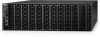
Dell Z9264F-ON EMC PowerSwitch Installation Guide March 2022 - Page 13
Rack mounting, Switch ground, Fans and airflow, Power, Storing components, Fan combinations
 |
View all Dell Z9264F-ON manuals
Add to My Manuals
Save this manual to your list of manuals |
Page 13 highlights
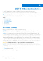
Rack mounting When you prepare your equipment rack, ensure that the rack is grounded. Ground the equipment rack to the same ground point the power service in your area uses. The ground path must be permanent. Switch ground Dell Technologies recommends grounding your switch. Use the Z9264F-ON switch in a CBN. For more information, see Ground lug assembly. Fans and airflow The Z9264F-ON switch fans support two airflow options: normal and reverse. Fan combinations Fan installation is done as part of the factory install based on stock keeping unit (SKU) type. The Z9264F-ON switch has SKUs that support the following configurations: ● AC or DC PSU with fan airflow from the I/O to the PSU-the red indicator is the normal airflow direction ● AC or DC PSU with fan airflow from the PSU to the I/O-the blue indicator is the reverse airflow direction Order the fans suitable to support your site's ventilation. Use a single type of airflow fan in your switch. Do not mix reverse and normal airflows in a single switch. For proper ventilation, position the switch in an equipment rack or cabinet with a minimum of 5 inches (12.7 cm) of clearance around the exhaust vents. When you install two Z9264F-ON switches near each other, to permit proper airflow, position the two switches at least 5 inches (12.7 cm) apart. The fan speed varies based on internal temperature monitoring. The Z9264F-ON switch never intentionally turns off the fans. For more information, see Fans. Power Connect the switch to the applicable power source using the appropriate power cable. An AC power cable is included with each PSU. When installing AC or DC switches, follow the requirements of the National Electrical Code, ANSI/NFPA 70, where applicable. The switch is powered-up when you connect the power cable between the switch and the power source. For more information, see Power supplies. CAUTION: Always disconnect the power cable before you service the power supply slots. The switch has multiple power cables. Before servicing, ensure that all power cables are disconnected. CAUTION: On an AC switch, use the power supply cable as the main disconnect device. Ensure that the socketoutlet is located and installed near the equipment and is accessible. NOTE: The software controls the module power. You do not see module LEDs when the switch powers up in ONIE. Storing components If you do not install your Z9264F-ON switch and components immediately, properly store the switch and all optional components using these guidelines: ● Storage location temperature must remain constant. The storage range is from -40°C to 70°C (-40° to 158°F). Site preparations 13
-
 1
1 -
2
-
3
-
4
-
5
-
6
-
7
-
 8
8 -
 9
9 -
 10
10 -
 11
11 -
 12
12 -
 13
13 -
 14
14 -
 15
15 -
 16
16 -
 17
17 -
 18
18 -
19
-
20
-
21
-
22
-
23
-
24
-
25
-
26
-
27
-
28
-
29
-
30
-
31
-
32
-
33
-
34
-
35
-
36
-
37
-
38
-
39
-
40
-
41
-
42
 |
 |