Denon AVR-2803S Operating Instructions - Page 17
Speaker, system, layout, System, Setup, Delay, Channel, Level, Digital, Assignment, Video, Dolby, - avr 2803 receiver
 |
View all Denon AVR-2803S manuals
Add to My Manuals
Save this manual to your list of manuals |
Page 17 highlights
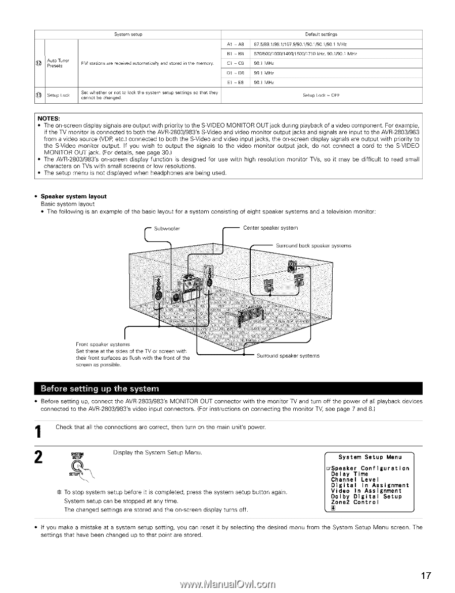
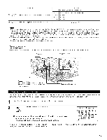
@ APuretosetTsuner _ Setup Lock System setup FM stations are received automatically and stored it1 the memory Set whether or not to lock tile system setup settlrlgs so that they ca_mot be changed A1 -- A8 B1 -- B8 C1 -- C8 D1 -- D8 E1 -- E8 Defauk settings 87 5/89 1/98 1/107 9/901/901/90//90/ MHz 520/600//000/1400/1500//710 90 1 MHz kHz, 90//90/ MHz 90 1 MHz 90 1 MHz Setup Lock = OFF NOTES: • The on-screen display signals are output with priority to the S-VIDEO MONITOR OUT jack during playback of a video component. For example, if the TV monitor is connected to both the AVR-2803/983'S S-Video and video monitor output jacks and signals are input to the AVR-2803/983 from a video source (VDP, etc.) connected to both the S-Video and video input jacks, the on-screen display signals are output with priority to the S-Video monitor output. If you wish to output the signals to the video monitor output jack, do not connect a cord to the S-VIDEO MONITOR OUT jack. (For details, see page 30.) • The AVR-2803/983'S on-screen display function is designed for use with high resolution monitor TVs, so it may be difficult to read small characters on TVs with small screens or low resolutions. • The setup menu is not displayed when headphones are being used. • Speaker system layout Basic system layout • The following is an example of the basic layout for a system consisting of eight speaker systems and a television monitor: Subwoofer Center speaker system Surround back speaker systems __ Front speaker systems Set these at the sides of the TV or screen with their front surfaces as flush with the front of the screen as possible Surround speaker systems • Before setting up, connect the AVR-2803/983's MONITOR OUT connector with the monitor TV and turn off the power of all playback devices connected to the AVR-2803/983's video input connectors. (For instructions on connecting the monitor TV, see page 7 and 8.} Check that all the connections are correct, then turn on the main unit's power. SETUp Display the System Setup Menu. To stop system setup before it is completed, press the system setup button again. System setup can be stopped at any time. The changed settings are stored and the on screen display turns off. System Setup Menu _Speaker Configuration Delay Time Channel Level Digital In Assignment Video In Assignment Dolby Digital Setup Zone2 Control • if you make a mistake at a system setup setting, you can reset it by selecting the desired menu from the System Setup Menu screen. The settings that have been changed up to that point are stored. 17
-
 1
1 -
2
-
3
-
4
-
5
-
6
-
7
-
8
-
9
-
10
-
11
-
 12
12 -
 13
13 -
 14
14 -
 15
15 -
 16
16 -
 17
17 -
 18
18 -
 19
19 -
 20
20 -
 21
21 -
 22
22 -
23
-
24
-
25
-
26
-
27
-
28
-
29
-
30
-
31
-
32
-
33
-
34
-
35
-
36
-
37
-
38
-
39
-
40
-
41
-
42
-
43
-
44
-
45
-
46
-
47
-
48
-
49
-
50
-
51
-
52
-
53
-
54
-
55
-
56
-
57
-
58
-
59
-
60
-
61
-
62
-
63
-
64
-
65
-
66
-
67
-
68
-
69
-
70
-
71
-
72
-
73
-
74
-
75
-
76
 |
 |