Denon AVR-2803S Operating Instructions - Page 9
are Eabeled Y, CB, CR, or Y, Pb, Pr, or Y, R+Y,B+Y.These terms - avr 2803 s
 |
View all Denon AVR-2803S manuals
Add to My Manuals
Save this manual to your list of manuals |
Page 9 highlights
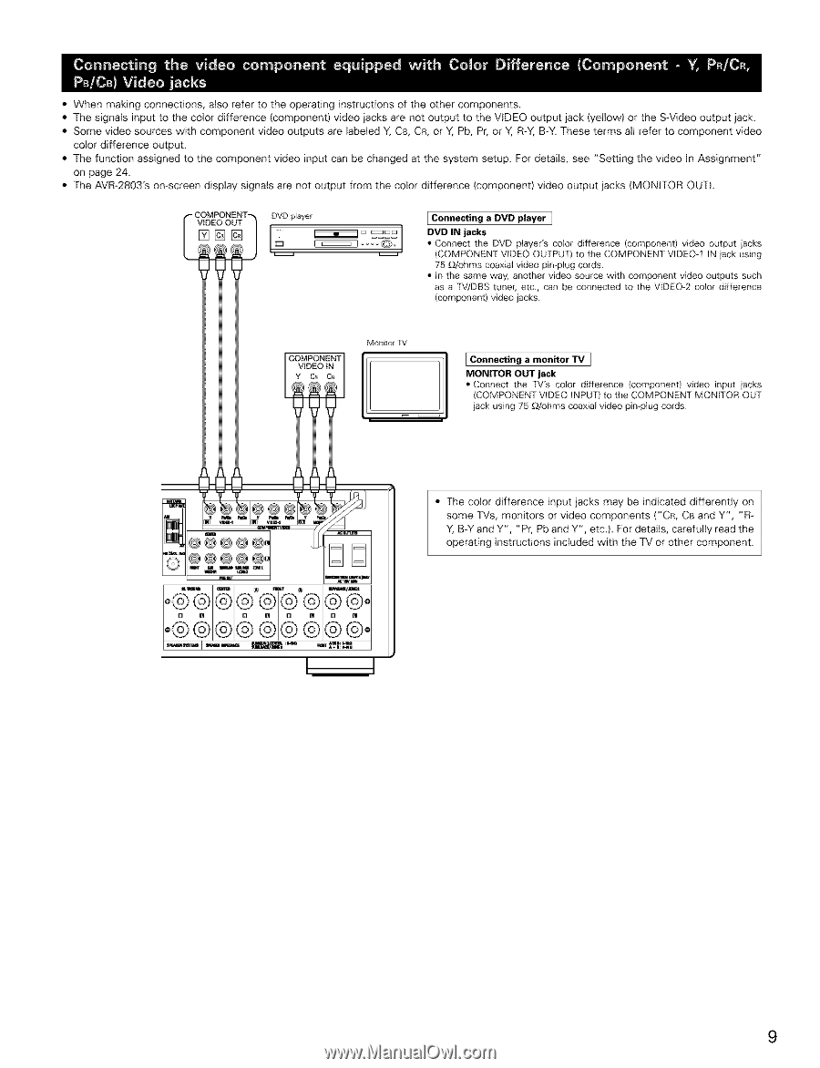
• When making connections, also refer to the operating instructions of the other components. • The signaEs input to the color difference (component) video jacks are not output to the VIDEO output jack (yellow) or the S+Video output jack. • Some video sources with component video outputs are Eabeled Y, CB, CR, or Y, Pb, Pr, or Y, R+Y,B+Y.These terms all refer to component video color difference output. • The function assigned to the component video input can be changed at the system setup. For details, see "Setting the video In Assignment" on page 24. • The AVR+2803's on+screen display signals are not output from the color difference {component) video output jacks {MONITOR OUT). VIDEO OUT DVD player +++++I+ Connecting a DVD player ] r++l++ ,DVD IN jacks • Connect the DVD player's color difference (component) video output iacks (COMPONENT VIDEO OUTPUT) to the COMPONENT VtDEO-I tN iack using 75 _dohms coaxial video pin-ptug cords¸ • In the same way, another video source with component video Outputs such as a TV/DBS tuner, etc, can be connected to the VEDEO-2 color difference (componentl video jacks¸ COMPONENT VIDEO iN Y C_ CA Monitol TV Connecting a monitor +IV ] MONITOR OUT jack • Connect the TV's color difference (component) video input iacks (COMPONENT VIDEO INPUT) to the COMPONENT MONETOR OUT jack using 75 OJohms coaxiaE video pimplug cords¸ • The color difference input jacks may be indicated differently on some TVs, monitors or video components ("CR, CB and Y', "R- Y, B-Y and Y", "Pr, Pb and Y", etc.). For details, carefully read the operating instructions included with the TV or other component. 9
-
 1
1 -
2
-
3
-
 4
4 -
 5
5 -
 6
6 -
 7
7 -
 8
8 -
 9
9 -
 10
10 -
 11
11 -
 12
12 -
 13
13 -
 14
14 -
15
-
16
-
17
-
18
-
19
-
20
-
21
-
22
-
23
-
24
-
25
-
26
-
27
-
28
-
29
-
30
-
31
-
32
-
33
-
34
-
35
-
36
-
37
-
38
-
39
-
40
-
41
-
42
-
43
-
44
-
45
-
46
-
47
-
48
-
49
-
50
-
51
-
52
-
53
-
54
-
55
-
56
-
57
-
58
-
59
-
60
-
61
-
62
-
63
-
64
-
65
-
66
-
67
-
68
-
69
-
70
-
71
-
72
-
73
-
74
-
75
-
76
 |
 |