Dewalt DXCMTB5590856 Instruction Manual - Page 11
Features
 |
View all Dewalt DXCMTB5590856 manuals
Add to My Manuals
Save this manual to your list of manuals |
Page 11 highlights
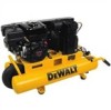
English FEATURES UNLOADER VALVE When the maximum air tank pressure is obtained, the unloader valve (H) will blow-off. This will cause the compressor to exhaust the air to the atmosphere and not the tank. The valve is preset by the manufacturer and must not be removed or modified in any way. Manual Lock: The manual lock allows you to manually unload the compressor with air pressure in the air tank. To operate the manual lock: Rotate the manual lock unloader lever to the open position to prevent air tank pressure F F buildup. Rotate manual lock unloader lever to the closed position after starting the engine to allow air tank pressure to build. NOTE: Air will not build in tank when manual OPEN CLOSED lock unloader lever in the open position. SAFETY VALVE This valve (I) is designed to prevent system failures I by relieving pressure from the system when the compressed air reaches a predetermined level. The valve is preset by the manufacturer and must not be removed or modified in any way. AIR INTAKE FILTER A The filter (A) is designed to clean air entering the pump. To ensure the pump continually receives a clean, cool, and dry air supply the filter must always be clean and the filter intake must be free from obstructions. AIR TANK DRAIN VALVES The drain valve (J) is used to remove moisture from the air tank after the air compressor is shut off. J AIR TANK PRESSURE GAUGE The air tank pressure gauge (D) indicates air pressure in the air tank. REGULATED PRESSURE GAUGE The regulated pressure gauge (E) indicates the air pressure available at the outlet side D of the regulator. This pressure is controlled E by the regulator and is always less or equal F to the air tank pressure. REGULATOR The regulator knob (F) controls the air pressure coming from the air tank. To Adjust Regulator: 1. Pull regulator knob (F) out to unlock. 2. Turn knob clockwise to increase regulated pressure and counterclockwise to decrease regulated pressure. 3. When desired pressure is shown on the regulated pressure gauge push knob in to lock. WARNING: Risk of Bursting. Too much air pressure causes a hazardous risk of bursting. Check the manufacturer's maximum pressure rating for air tools and accessories. The regulator outlet pressure must never exceed the maximum pressure rating. THROTTLE CONTROL When maxim um air tank pressure is reached and the unloader valve vents air, it activates the throttle control on the engine. 11
-
 1
1 -
2
-
3
-
4
-
5
-
 6
6 -
 7
7 -
 8
8 -
 9
9 -
 10
10 -
 11
11 -
 12
12 -
 13
13 -
 14
14 -
 15
15 -
 16
16 -
17
-
18
-
19
-
20
-
21
-
22
-
23
-
24
-
25
-
26
-
27
-
28
-
29
-
30
-
31
-
32
-
33
-
34
-
35
-
36
-
37
-
38
-
39
-
40
-
41
-
42
-
43
-
44
-
45
-
46
-
47
-
48
-
49
-
50
-
51
-
52
-
53
-
54
-
55
-
56
-
57
-
58
-
59
-
60
-
61
-
62
-
63
-
64
-
65
-
66
-
67
-
68
-
69
-
70
-
71
-
72
-
73
-
74
-
75
-
76
-
77
-
78
-
79
-
80
-
81
-
82
-
83
-
84
-
85
-
86
-
87
-
88
 |
 |
