Dewalt DXGNR7000 Instruction Manual - Page 9
Assembly, Unpacking, Install Accessory Kits, Battery Replacement/Connection, Table -1. Contents - battery charger
 |
View all Dewalt DXGNR7000 manuals
Add to My Manuals
Save this manual to your list of manuals |
Page 9 highlights
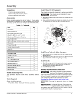
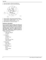
Assembly Unpacking • Remove all packaging material. • Remove separate accessory kit box. • Remove generator from carton. Accessories Check contents against the list in Table -1. If any parts are missing or damaged, or if any problems occur during assembly, call the Generator Helpline at 1-888-431-6871. Table -1. Contents Item Qty. Generator 1 Owner's Manual 1 Product Registration Card (English, Spanish, and French) 3 Service and Emissions Warranty 1 Liter SAE 30 Oil 1 Battery Charger (electric start models) 1 Wheel (A) 2 Frame Foot (B) 2 Handle Assembly (C) 1 Axle (D) 1 Hardware Bag Rubber Foot (E) 2 Hair Pin (F) 2 1/2" Flat Washer (G) 2 M8 Carriage Bolt (H) 2 M8 Bolt (long) (J) 4 M8 Hex Flange Nut (K) 8 Axle Bracket (L) 2 M6 bolt (M) 4 Install Accessory Kits The generator requires some minor assembly before use. Tools Required Obtain the following tools: • Two 8mm, 10mm, 12mm and 13mm box wrenches Install Wheel Kit (If Equipped) The wheels are specially designed to enhance portability. NOTICE: The wheels are not intended for overthe-road use. 1. Slide M6 bolt (M) through holes in frame rail. Install into axle bracket (L). 2. Slide axle (D) through axle bracket (L), wheel (A), and into ½" flat washer (G). Insert hair pin (F) through axle (D). J K M B K A D E L H C F G 000757 Install frame foot and rubber bumpers. 1. Slide rubber foot (E) through frame foot (B). Install locking flange nuts (K). 2. Slide M8 bolt (J) through holes in frame rail. Slide frame foot (B) onto M8 bolts. Install locking flange nuts (K). Install Handle 1. Slide M8 carriage bolt (H) through handle bracket and handle assembly (C) by first inserting the bolt through the square hole in the handle assembly (C). 2. Install M8 flange nut (K). Battery Replacement/Connection NOTICE: The battery shipped with the generator has been fully charged. A battery may lose some charge when not in use for prolonged periods of time. If battery is unable to crank engine, plug in the 12V charger included in the accessory box (see Charging the Battery (electric start units only) IMPORTANT: Running the generator does not charge battery. WARNING Accidental Start-up. Disconnect the negative battery cable, then the posi- tive battery cable when working on unit. Failure to do so could result in death or serious injury. Owner's Manual for Portable Generator 5
-
 1
1 -
2
-
3
-
 4
4 -
 5
5 -
 6
6 -
 7
7 -
 8
8 -
 9
9 -
 10
10 -
 11
11 -
 12
12 -
 13
13 -
 14
14 -
15
-
16
-
17
-
18
-
19
-
20
-
21
-
22
-
23
-
24
-
25
-
26
-
27
-
28
-
29
-
30
-
31
-
32
-
33
-
34
-
35
-
36
-
37
-
38
-
39
-
40
-
41
-
42
-
43
-
44
-
45
-
46
-
47
-
48
-
49
-
50
-
51
-
52
-
53
-
54
-
55
-
56
-
57
-
58
-
59
-
60
-
61
-
62
-
63
-
64
-
65
-
66
-
67
-
68
-
69
-
70
-
71
-
72
 |
 |
