Dynex DX-24L230A12 User Manual (English) - Page 10
Description
 |
View all Dynex DX-24L230A12 manuals
Add to My Manuals
Save this manual to your list of manuals |
Page 10 highlights
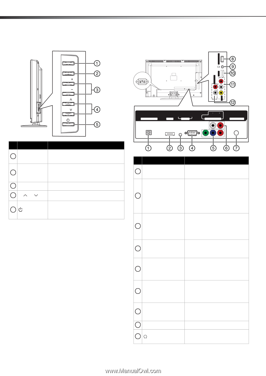
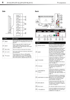
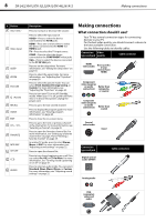
6 DX-24L230A12/DX-32L220A12/DX-46L261A12 TV components Side MENU INPUT VOL VOL CH CH SERVICE PORT Back AC IN R AUDIO R AUDIO OUT AUDIO HDMI 2 L L VIDEO AV IN DIGITAL OUTPUT AUDIO VGA HDMI 1 PC IN L AUDIO R Y PB PR COMPONENT IN ANT/ CABLE IN # Item 1 MENU 2 INPUT 3 VOL+/VOL- 4 CH /CH 5 (Power) Description Press to open the on-screen menu. For more information, see "Navigating the menus" on page 20. Press to open the INPUT SOURCE list and select a video input source. For more information, see "Selecting the video input source" on page 19. Press to increase or decrease the volume. Press to go to the next or previous channel in the channel list. Press to turn your TV on or off (standby mode). When your TV is in standby mode, power still flows through it. To completely disconnect power, unplug the power cord. # Item Description 1 DIGITAL OUTPUT Connect a digital audio amplifier to this jack. For more information, see "Using digital audio" on page 17. 2 HDMI1 Connect an HDMI device to this jack. An HDMI cable carries both video and sound. You do not need to make an audio connection for an HDMI device. For more information, see "Connecting a DVD or Blu-ray player" on page 12, or "Connecting an HDMI or DVI device (best)" on page 13. 3 PC IN AUDIO Connect the audio for a computer or a DVI device to this jack. For more information, see "Connecting a computer" on page 15 or "Connecting an HDMI or DVI device (best)" on page 13. 4 PC IN VGA Connect the video for a computer to this jack. For more information, see "Connecting a computer" on page 15. COMPONENT IN 5 Y, PB, PR Connect the video for a component video device to these jacks. For more information, see "Connecting a component video device (better)" on page 13. Connect the audio for a component video device connected to the Y, PB, 6 COMPONENT L/R AUDIO PR jacks. For more information, see "Connecting a component video device (better)" on page 13. 7 ANT/CABLE IN Connect an antenna or cable TV to this jack. For more information, see "Connecting an antenna or cable TV (no box)" on page 12. 8 Service port For software update only. Do not use. 9 (headphone) Connect headphones to this jack. For more information, see "Connecting headphones" on page 16.
-
 1
1 -
2
-
3
-
4
-
 5
5 -
 6
6 -
 7
7 -
 8
8 -
 9
9 -
 10
10 -
 11
11 -
 12
12 -
 13
13 -
 14
14 -
 15
15 -
16
-
17
-
18
-
19
-
20
-
21
-
22
-
23
-
24
-
25
-
26
-
27
-
28
-
29
-
30
-
31
-
32
-
33
-
34
-
35
-
36
-
37
-
38
-
39
-
40
-
41
-
42
-
43
-
44
-
45
-
46
-
47
-
48
 |
 |