E-Z-GO Shuttle 22 TXT - Electric Owner Manual - Page 35
NOTICE, An ungrounded electrical device may become a physical hazard that could result in an elec
 |
View all E-Z-GO Shuttle 22 TXT - Electric manuals
Add to My Manuals
Save this manual to your list of manuals |
Page 35 highlights
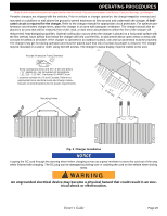
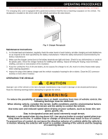
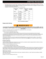
OPERATING PROCEDURES Read all of this manual to become thoroughly familiar with this vehicle. Pay particular attention to all Notices, Cautions, Warnings, and Dangers. Portable chargers are shipped with the vehicles. Prior to vehicle or charger operation, the charger must be removed and mounted on a platform or wall above the ground to permit maximum air flow around and underneath the charger. A dedicated circuit is required for the charger. Refer to the charger manual for appropriate circuit protection. For optimum performance and shortest charge times, place the charger in an area with adequate ventilation. The charger should also be placed in an area that will be relatively free of dirt, mud, or dust since accumulations within the fins of the charger will reduce their heat-dissipating qualities. Optimal cooling also occurs when the charger is placed on a horizontal surface with the fins vertical. More airflow from below the charger will help cool the fins, so placement above open areas or areas with cut-outs for airflow is desirable. If the charger is operated in an outdoor location, rain and sun protection must be provided. The charger may get hot during operation and must be placed such that risk of contact by people is reduced. The charger may be mounted on a wall or shelf using #10-M5 screws. The charger's status display must be visible to the user. Provide Protection From Elements Provide Protection From Elements Keep cooling fins clean and free of dirt and debris NEMA 15 - 5R Grounded AC Receptacle 110 - 120 VAC. Dedicated 15 AMP Circuit Locations outside the US and Canada: Reference Keep cooling fins calepparonpriaatnedlocfarleeelecotrifcadl cirotdeaanndd cdhaergberrimsanuNEMA 15 - 5fRactuGrerroreuconmdmeedndAatiConsRfoer AcCeppotwaecrlreequirements 110 - 120 VAC. Dedicated 15 AMP Circuit Locations outside the US and Canada: Reference appropriate local electrical code anMdoucnthinag rHgoleesr manufacturer recommendations for AC power requirements Hanging Holes Hanging Holes (7.893c.1m" ) Mounting Holes (7.893c.1m" ) Fig. 3 Charger Installation NOTICE Looping the DC cord through the steering wheel when charging serves as a good reminder to store the cord out of the way when finished with charging. The DC plug can be damaged by driving over or catching the cord on the vehicle when driving away. An ungrounded electrical device may become a physical hazard that could result in an electrical shock or electrocution. Owner's Guide Page 29
-
 1
1 -
2
-
3
-
4
-
5
-
6
-
7
-
8
-
9
-
10
-
11
-
12
-
13
-
14
-
15
-
16
-
17
-
18
-
19
-
20
-
21
-
22
-
23
-
24
-
25
-
26
-
27
-
28
-
29
-
 30
30 -
 31
31 -
 32
32 -
 33
33 -
 34
34 -
 35
35 -
 36
36 -
 37
37 -
 38
38 -
 39
39 -
 40
40 -
41
-
42
-
43
-
44
-
45
-
46
-
47
-
48
-
49
-
50
-
51
-
52
-
53
-
54
-
55
-
56
-
57
-
58
-
59
-
60
-
61
-
62
-
63
-
64
-
65
-
66
-
67
-
68
-
69
-
70
-
71
-
72
 |
 |
