Electrolux ELFG7437AG Complete Owners Guide - Page 22
Connecting the gas, Connecting the water, INSTALLATION
 |
View all Electrolux ELFG7437AG manuals
Add to My Manuals
Save this manual to your list of manuals |
Page 22 highlights
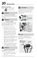
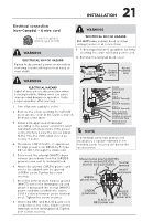
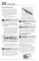
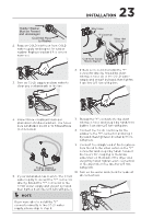
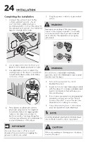
22 INSTALLATION Connecting the gas This gas dryer comes from the factory with natural gas burner components installed. DO NOT operate this gas dryer, using LP (liquid propane) gas, unless the LP gas conversion kit has been properly installed by a qualified service personnel. Improper gas installation or LP conversion kit installation could result in injury or even death. 1. Remove the shipping cap from gas pipe at the rear of the dryer. WARNING DO NOT connect the dryer to L.P. gas service without converting the gas valve. An L.P. conversion kit PN# PCK4200 (not included) must be installed by a qualified gas technician. to dryer from gas supply Shutoff Valve - Open position 4. Check for gas system leaks with a manometer. If a manometer is not available, test all connections by brushing on a soapy water solution. WARNING EXPLOSION HAZARD NEVER test for gas leaks with an open flame. 2. Connect a 1/2 inch (1.27 cm) I.D. semirigid or approved pipe from gas supply line to the 3/8 inch (0.96 cm) pipe located on the back of the dryer. Use a 1/2 inch to 3/8 inch (1.27 cm to 0.96 cm) reducer for the connection. Apply an approved thread sealer that is resistant to the corrosive action of liquefied gases on all pipe connections. Manual Shutoff Valve Flare GAS FLOW Flare Union Union Open Nipple Flexible Inlet Pipe on Closed Connector Back of Dryer All connections must be wrench-tightened 3. Open the shutoff valve in the gas supply line to allow gas to flow through the pipe. Wait a few minutes for gas to move through the gas line. IMPORTANT The supply line must be equipped with an approved manual shutoff valve. This valve should be located in the same room as the dryer and should be in a location that allows ease of opening and closing. DO NOT block access to the gas shutoff valve. IMPORTANT Installation to the gas service must follow local codes and ordinances and the latest edition of the National Fuel Gas Code ANSI Z223.1/NFPA 54 or in Canada, CSA B149.1. Connecting the water (steam models only) WARNING Periodically inspect all water inlet hoses for water leaks, wear, cuts, corrosion and bulges. Replace all hoses, if any sign of the above is visible. All hoses should be replaced every 5 years to reduce the risk of hose failures. Water supply requirements Cold water faucet MUST be installed within 42 inches (107 cm) of your dryer's water inlet. The faucet MUST be 3/4 inch (1.9 cm) with threading for laundry hose connection. Water pressure MUST be between 20 and 120 psi. Your water department can advise you of your water pressure. 1. Turn off COLD water supply to washer.
-
 1
1 -
2
-
3
-
4
-
5
-
6
-
7
-
8
-
9
-
10
-
11
-
12
-
13
-
14
-
15
-
16
-
 17
17 -
 18
18 -
 19
19 -
 20
20 -
 21
21 -
 22
22 -
 23
23 -
 24
24 -
 25
25 -
 26
26 -
 27
27 -
28
-
29
-
30
-
31
-
32
-
33
-
34
-
35
-
36
-
37
-
38
-
39
-
40
-
41
-
42
-
43
-
44
-
45
-
46
-
47
-
48
 |
 |
