Epson ActionNote 890CX User Manual - Page 63
card straight into the connector., the system board Then gently push
 |
View all Epson ActionNote 890CX manuals
Add to My Manuals
Save this manual to your list of manuals |
Page 63 highlights
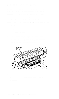
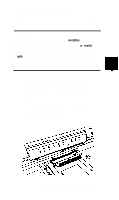
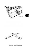
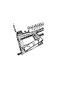
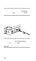
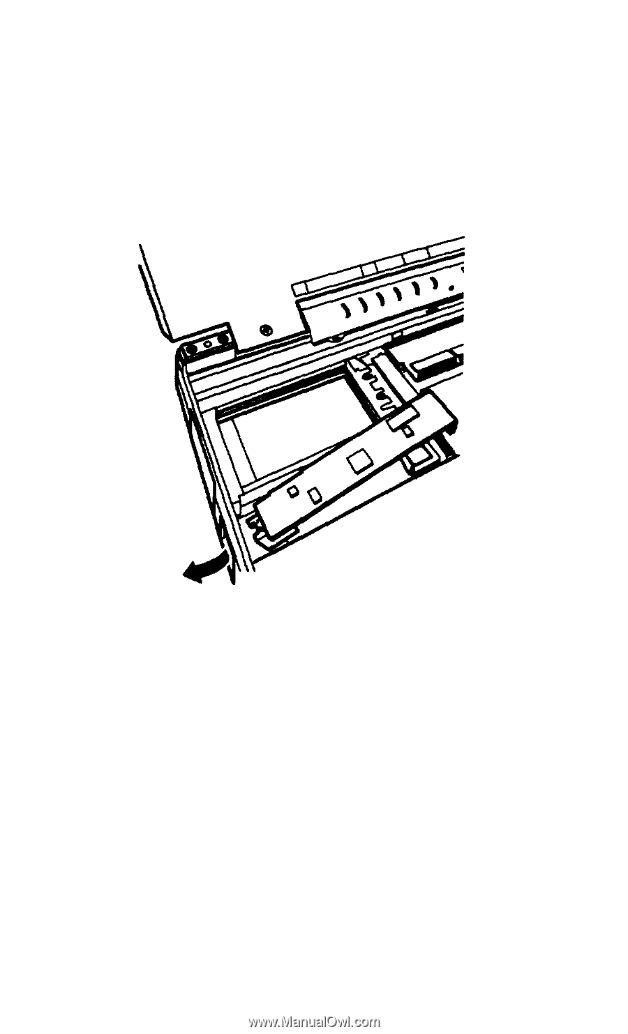
4. Insert the phone jack end of the fax/ modem card or the LED window of the infrared card into the port opening and align the connector on the card with the connector on the system boar4 as shown below. 5. Make sure the pins in the connector are directly over the holes in the connector on the system board Then gently push the card straight into the connector. 6. If you are installing an infrared device, you must cover the port opening with the clear plastic cover provided with the device. 5-16 Upgrading Internal Components
-
 1
1 -
2
-
3
-
4
-
5
-
6
-
7
-
8
-
9
-
10
-
11
-
12
-
13
-
14
-
15
-
16
-
17
-
18
-
19
-
20
-
21
-
22
-
23
-
24
-
25
-
26
-
27
-
28
-
29
-
30
-
31
-
32
-
33
-
34
-
35
-
36
-
37
-
38
-
39
-
40
-
41
-
42
-
43
-
44
-
45
-
46
-
47
-
48
-
49
-
50
-
51
-
52
-
53
-
54
-
55
-
56
-
57
-
 58
58 -
 59
59 -
 60
60 -
 61
61 -
 62
62 -
 63
63 -
 64
64 -
 65
65 -
 66
66 -
 67
67 -
 68
68 -
69
-
70
-
71
-
72
-
73
-
74
-
75
-
76
-
77
-
78
-
79
-
80
-
81
-
82
-
83
-
84
-
85
-
86
-
87
-
88
-
89
-
90
-
91
-
92
-
93
-
94
-
95
-
96
-
97
-
98
-
99
-
100
-
101
-
102
-
103
-
104
-
105
-
106
-
107
-
108
-
109
-
110
-
111
-
112
-
113
 |
 |
4.
5.
6.
Insert the phone jack end of the fax/
modem card or the LED window of the
infrared card into the port opening and
align the connector on the card with the
connector on the system boar4 as shown
below.
Make sure the pins in the connector are
directly over the holes in the connector on
the system board Then gently push the
card straight into the connector.
If you are installing an infrared device,
you must cover the port opening with the
clear plastic cover provided with the
device.
5-16 Upgrading Internal Components