Epson T-1000 User Manual - Page 81
Appendix A-7, shown below.
 |
View all Epson T-1000 manuals
Add to My Manuals
Save this manual to your list of manuals |
Page 81 highlights
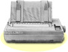
Installing an lnterface 3. Plug the interface board into the connector marked CN2 on the main circuit board of the printer. 4. Secure the board to the three supports with the screws provided, as shown below. Appendix A-7
-
 1
1 -
2
-
3
-
4
-
5
-
6
-
7
-
8
-
9
-
10
-
11
-
12
-
13
-
14
-
15
-
16
-
17
-
18
-
19
-
20
-
21
-
22
-
23
-
24
-
25
-
26
-
27
-
28
-
29
-
30
-
31
-
32
-
33
-
34
-
35
-
36
-
37
-
38
-
39
-
40
-
41
-
42
-
43
-
44
-
45
-
46
-
47
-
48
-
49
-
50
-
51
-
52
-
53
-
54
-
55
-
56
-
57
-
58
-
59
-
60
-
61
-
62
-
63
-
64
-
65
-
66
-
67
-
68
-
69
-
70
-
71
-
72
-
73
-
74
-
75
-
 76
76 -
 77
77 -
 78
78 -
 79
79 -
 80
80 -
 81
81 -
 82
82 -
 83
83 -
 84
84 -
 85
85 -
 86
86 -
87
-
88
-
89
-
90
-
91
-
92
-
93
-
94
 |
 |

Installing an lnterface
3.
Plug the interface board into the connector marked CN2 on the main
circuit board of the printer.
4.
Secure the board to the three supports with the screws provided, as
shown below.
Appendix A-7